


Chapter 14
14-19
14.3 Scanning System
14.3.1 After Replacing the Reader Controller PCB
0015-9932
iR5065 / iR 5055 / iR5075 / iR5075N / iR5065N / iR5055N
Be sure to generate the latest P-PRINT printout before replacing the reader
controller PCB.
- If you are initializing the RAM on the reader controller without replacing
the PCB
Using the SST, upload the backup data of R-CON; initialize the RAM, and
then download the data, thus eliminating the need for the following.
1) Using the SST, download the latest system software (R-CON).
2) Make the following selections in the service mode: COPIER > FUNC-
TION > CLEAR > R-CON. Then, press the OK key to execute RAM in-
itialization. Thereafter, turn off and then back on the main power.
3) Enter the appropriate settings for the following items in the service mode:
a. setting indicated on the service label (found behind the reader unit front
cover)
a-1. image read start position adjustment (X direction; in fixed reading
mode)
COPIER>ADJUST>ADJ-XY>ADJ-X
a-2 image read start position adjustment (Y direction; in fixed reading
mode)
COPIER>ADJUST>ADJ-XY>ADJ-Y
a-3 shading position adjustment (in fixed reading mode)
COPIER>ADJUST>ADJ-XY>ADJ-S
a-4 feeder mode main scanning position adjustment
COPIER>ADJUST>ADJ-XY>ADJ-Y-DF
a-5 ADF stream reading CCD reading position
COPIER>ADJUST>ADJ-XY>STRD-POS
a-6 density manipulating value adjustment
COPIER>ADJUST>CCD>DFCH-G2
COPIER>ADJUST>CCD>DFCH-G10
(After inputs it, execute COPIER>FUNCTION>DF-LNR)
The machine retains ADF-related service data in the RAM of its reader con-
troller.
ADF adjustment is necessary whenever you have replaced the reader con-
troller or initialized the RAM.
b. original stop position adjustment (X direction) (stream reading)
FEEDER>ADJSUT>DOCST
c. original feed speed (magnification) adjustment
FEEDER>ADUST>LA-SPEED
4) Make adjustments using the following service mode items:
a. ADF sensor sensitivity adjustment
FEEDER>FUNCTION>SENS-INT
b. tray width adjustment
FEEDER>FUNCTION>TRY-A4
FEEDER>FUNCTION>TRY-A5R
FEEDER>FUNCTION>TRY-LTR
FEEDER>FUNCTION>TRY-LTRR
c. white plate data adjustment
COPIER>FUNCTION>CCD>CCD-ADJ
d. ADF white level adjustment
COPIER>FUNCTION>CCD>DF-WLVL1
COPIER>FUNCTION>CCD>DF-WLVL2
Be sure to perform white plate data adjustment before performing ADF
white level adjustment.
After having made the foregoing adjustments, put the P-PRINT printout in
the service book case, replacing the previous P-PRINT printout.
14.3.2 When Replacing the CCD Unit
0015-9938
iR5065 / iR 5055 / iR5075 / iR5075N / iR5065N / iR5055N
Perform the following steps after replacing the CCD unit.
1) Enter the correction values to be described on the label included in the
CCD unit (the 2 following items) in the service mode.
- COPIER > ADJUST > CCD > DFCH2G2
- COPIER > ADJUST > CCD > DFCH2G10
2) Transcribe the above correction values to the service label at the back of
the front cover of the host machine.
3) Execute the following in the service mode.
3-1) White plate data adjustment (COPIER > FUNCTION > CCD > CCD-
ADJ)
3-2) ADF white level adjustment (COPIER > FUNCTION > CCD > DF-
WLVL1/2)
Be sure to perform white plate data adjustment before performing ADF
white level plate.
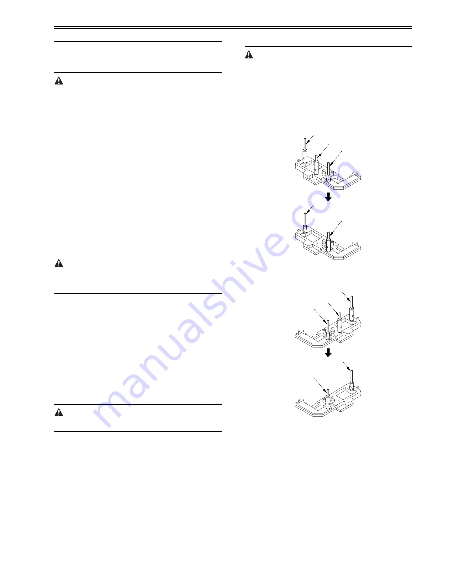
14.3.3 Adjusting the Position of the No. 1/No. 2 Mirror
Base
0015-9941
iR5065 / iR 5055 / iR5075 / iR5075N / iR5065N / iR5055N
1) Arrange the mirror positioning tool (FY9-3009-040) so that it is ready for
use in the machine (by changing the pin position; REAR).
F-14-33
2) Arrange the mirror positioning tool so that it is ready for use in the ma-
chine (by changing the pin position; FRONT).
F-14-34
3) Fit the pins of the mirror positioning tool (front [2]; rear [3]) into the ap-
propriate holes [1] of the No. 1/No. 2 mirror base.
[A]
[B]
[C]
[B]
[A]
[A]
[B]
[C]
[B]
[A]
Summary of Contents for iR5055
Page 1: ...Feb 29 2008 Service Manual iR5075 5065 5055 Series ...
Page 2: ......
Page 6: ......
Page 27: ...Contents 19 1 2 List of Solvents Oils 19 2 ...
Page 28: ...Contents ...
Page 29: ...Chapter 1 Introduction ...
Page 30: ......
Page 32: ......
Page 59: ...Chapter 2 Installation ...
Page 60: ......
Page 104: ...Chapter 2 2 42 F 2 156 2 1 ...
Page 105: ...Chapter 3 Basic Operation ...
Page 106: ......
Page 108: ......
Page 115: ...Chapter 4 Main Controller ...
Page 116: ......
Page 118: ......
Page 135: ...Chapter 5 Original Exposure System ...
Page 136: ......
Page 169: ...Chapter 6 Laser Exposure ...
Page 170: ......
Page 172: ......
Page 178: ......
Page 179: ...Chapter 7 Image Formation ...
Page 180: ......
Page 184: ......
Page 217: ...Chapter 8 Pickup Feeding System ...
Page 218: ......
Page 274: ......
Page 275: ...Chapter 9 Fixing System ...
Page 276: ......
Page 280: ......
Page 320: ......
Page 321: ...Chapter 10 External and Controls ...
Page 322: ......
Page 326: ......
Page 336: ...Chapter 10 10 10 F 10 7 2 Remove the check mark from SNMP Status Enabled ...
Page 337: ...Chapter 10 10 11 F 10 8 ...
Page 361: ...Chapter 11 MEAP ...
Page 362: ......
Page 364: ......
Page 409: ...Chapter 12 e maintenance imageWARE Remote ...
Page 410: ......
Page 412: ......
Page 421: ...Chapter 13 Maintenance and Inspection ...
Page 422: ......
Page 424: ......
Page 433: ...Chapter 14 Standards and Adjustments ...
Page 434: ......
Page 464: ......
Page 465: ...Chapter 15 Correcting Faulty Images ...
Page 466: ......
Page 468: ......
Page 496: ......
Page 497: ...Chapter 16 Self Diagnosis ...
Page 498: ......
Page 500: ......
Page 528: ......
Page 529: ...Chapter 17 Service Mode ...
Page 530: ......
Page 532: ......
Page 600: ......
Page 601: ...Chapter 18 Upgrading ...
Page 602: ......
Page 604: ......
Page 636: ...Chapter 18 18 32 F 18 59 2 Select the data to download F 18 60 3 Click Start ...
Page 638: ......
Page 639: ...Chapter 19 Service Tools ...
Page 640: ......
Page 642: ......
Page 645: ...Feb 29 2008 ...
Page 646: ......


