


Chapter 17
17-30
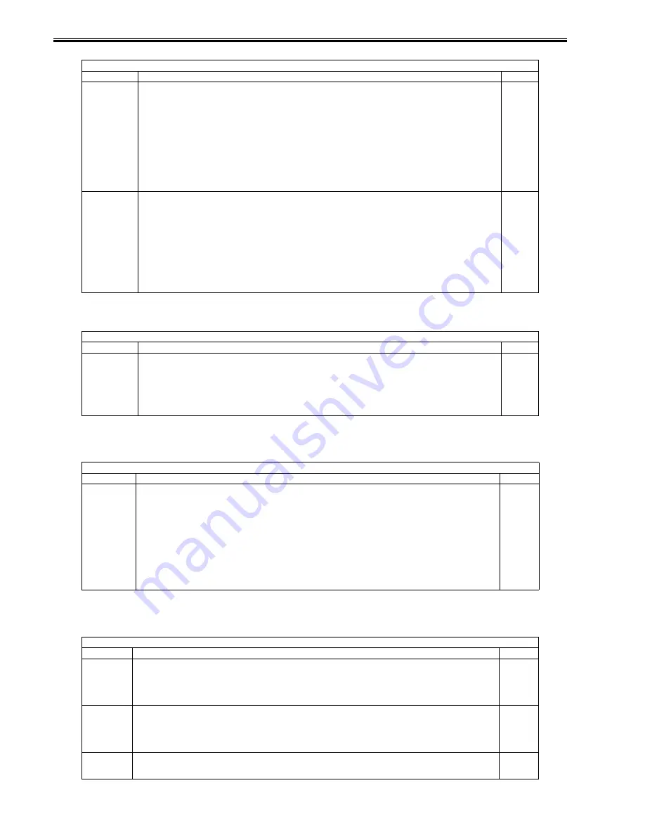
T-17-36
<CLEANING>
T-17-37
<FIXING>
T-17-38
<PANEL>
T-17-39
COPIER > FUNCTION > CST
Sub-item
Description
Level
C3-STMTR
C3-A4R
C4-STMTR
C4-A4R
Use it to register the paper width basic value of the cassette 3/4.
STMTR width: 139.5 mm; A4R width: 210 mm
To make fine adjustments after registering a value, use the following: ADJUST>CST-ADJ>C3-STMTR, C3-A4R, C4-STMTR,
C4-A4R.
Procedure
1) Put STMTR paper in the cassette, and adjust the slide guide plate to the width.
2) Select C3-STMTR (C4-STMTR) to highlight, and press the OK key so that the machine executes auto adjustment and register
the value.
3) Likewise, repeat steps 1) and 2) to register the basic value for A4R.
1
MF-A4R
MF-A6R
MF-A4
Use it to register the paper width basic value for the manual feed tray.
A4R width: 210 mm; A6R: 105 mm; A4 width: 297 mm
To make fine adjustments after registering a basic value, use the following: COPIER>ADJUST>CST-ADJ>MF-A4R, MF-A6R,
MF-A4.
Procedure
1) Put A4R paper in the manual feed tray, and adjust the size guide to the width.
2) Select MF-A4R to highlight, and press the OK key so that the machine executes auto adjustment and register the value.
3) Likewise, repeat steps 1) and 2) for A6R and A4.
1
COPIER > FUNCTION > CLEANING
Sub-item
Description
Level
WIRE-CLN
Clean all charging wires 5 times (5 trips) all at the same time.
Procedure
1) Select the item to highlight, and press the OK key.
2) See that the notation changes to 'ACTIVE', indicating that the charging wires are being cleaned.
3) See that the machine stops cleaning automatically. (To stop in the middle, press the OK key.)
1
COPIER > FUNCTION > FIXING
Sub-item
Description
Level
NIP-CHK
Use it to generate printouts for automatic measurement of the fixing nip width.
Procedure
1) Make about 20 A4 prints.
2) Put A4 plain or recycled paper in the manual feed tray.
3) Select the item to highlight, and press the OK key.
4) See that the paper is picked from the manual feed tray, held in the fixing nip area, and discharged in about 20 sec.
5) Check the nip width of the discharged paper: if b is from 4.5 to 6.5 mm, the nip may be considered normal. In the event of a
fixing fault or wrinkling and if the difference between the front b and the rear c is appreciable, go to step 6) to make adjustments.
6) Tighten the screw found on the side with the narrower nip; then, loosen the other screw to the same degree (so that the nip width
is identical between front and rear).
1
COPIER > FUNCTION > PANEL
Sub-item
Description
Level
LCD-CHK
Use it to check for missing dots in the LCD.
Procedure
1) Select the item, and press the OK key to start. See that the front of the touch panel starts to go on in the following order: white,
black, red, green, blue.
2) Press the Stop key to end the operation.
1
LED-CHK
Use it to check the activation of the LEDs on the control panel.
Procedure
1) Select the item, an press the OK key to start. See that the LEDs go on in sequence.
2) Press [LED-off] to end the operation.
1
LED-OFF
Check the LEDs on the control panel.
Procedure
1) Select the item to end the operation for LED-CHK.
1
Summary of Contents for iR5055
Page 1: ...Feb 29 2008 Service Manual iR5075 5065 5055 Series ...
Page 2: ......
Page 6: ......
Page 27: ...Contents 19 1 2 List of Solvents Oils 19 2 ...
Page 28: ...Contents ...
Page 29: ...Chapter 1 Introduction ...
Page 30: ......
Page 32: ......
Page 59: ...Chapter 2 Installation ...
Page 60: ......
Page 104: ...Chapter 2 2 42 F 2 156 2 1 ...
Page 105: ...Chapter 3 Basic Operation ...
Page 106: ......
Page 108: ......
Page 115: ...Chapter 4 Main Controller ...
Page 116: ......
Page 118: ......
Page 135: ...Chapter 5 Original Exposure System ...
Page 136: ......
Page 169: ...Chapter 6 Laser Exposure ...
Page 170: ......
Page 172: ......
Page 178: ......
Page 179: ...Chapter 7 Image Formation ...
Page 180: ......
Page 184: ......
Page 217: ...Chapter 8 Pickup Feeding System ...
Page 218: ......
Page 274: ......
Page 275: ...Chapter 9 Fixing System ...
Page 276: ......
Page 280: ......
Page 320: ......
Page 321: ...Chapter 10 External and Controls ...
Page 322: ......
Page 326: ......
Page 336: ...Chapter 10 10 10 F 10 7 2 Remove the check mark from SNMP Status Enabled ...
Page 337: ...Chapter 10 10 11 F 10 8 ...
Page 361: ...Chapter 11 MEAP ...
Page 362: ......
Page 364: ......
Page 409: ...Chapter 12 e maintenance imageWARE Remote ...
Page 410: ......
Page 412: ......
Page 421: ...Chapter 13 Maintenance and Inspection ...
Page 422: ......
Page 424: ......
Page 433: ...Chapter 14 Standards and Adjustments ...
Page 434: ......
Page 464: ......
Page 465: ...Chapter 15 Correcting Faulty Images ...
Page 466: ......
Page 468: ......
Page 496: ......
Page 497: ...Chapter 16 Self Diagnosis ...
Page 498: ......
Page 500: ......
Page 528: ......
Page 529: ...Chapter 17 Service Mode ...
Page 530: ......
Page 532: ......
Page 600: ......
Page 601: ...Chapter 18 Upgrading ...
Page 602: ......
Page 604: ......
Page 636: ...Chapter 18 18 32 F 18 59 2 Select the data to download F 18 60 3 Click Start ...
Page 638: ......
Page 639: ...Chapter 19 Service Tools ...
Page 640: ......
Page 642: ......
Page 645: ...Feb 29 2008 ...
Page 646: ......


