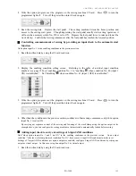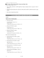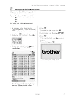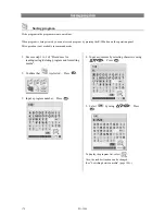
CHAPTER 5 EXTENDED OPTION OUTPUT
PD-3000
169
Creating an I/O allocation table
Allocate the selected hardware to complete the table.
Table of option output
Allocation Connector
Pin No.
Option output
No.
Name Description
Connector
No.
24V
1
5
6
2
3
P12 (AIR1)
10
11
4
1
5
2
6
3
7
4
8
5
9
6
10
7
11
P25 (AIR2)
8
9
10
12
8
13
4
14
3
15
2
16
P12 (AIR1)
1
10
11
17
1
18
2
19
3
20
P26 (AIR3)
4
5
Table of option input
Allocation Connector
Pin No.
Option input No.
Name Description
Connector
No.
24V 0V
1
2 3 1
2
5 6 4
3
8 9 7
4
11
12
10
5
P23 (EXIN1)
14 15 13
6
2 3 1
7
5 6 4
8
8 9 7
9
11
12
10
10
P24 (EXIN2)
14 15 13
11
2 1 3
12
P10
(SENSOR2)
5 4 6
13
P12
(AIR1)
12
11
9
14
P8
(SENSOR1)
11
10
12
Summary of Contents for PD-3000
Page 8: ...PD 3000 ...
Page 9: ...PD 3000 Chapter 1 Read Me ...
Page 12: ...CHAPTER 1 READ ME 4 PD 3000 ...
Page 13: ...PD 3000 Chapter 2 Setting Up Your Programmer ...
Page 28: ...CHAPTER 2 SETTING UP YOUR PROGRAMMER 20 PD 3000 ...
Page 29: ...PD 3000 Chapter 3 Programming with Icons ...
Page 95: ...PD 3000 Chapter 4 Programming with Commands ...
Page 152: ...CHAPTER 4 PROGRAMMING WITH COMMANDS 144 PD 3000 ...
Page 153: ...PD 3000 Chapter 5 Extended Option Output ...
Page 181: ...PD 3000 Chapter 6 Reading Saving Deleting Program and Formatting Media ...
Page 190: ...CHAPTER6 READING SAVING DELETING PROGRAM AND FORMATTING MEDIA 182 PD 3000 ...
Page 191: ...Chapter 7 Checking Copying Moving Changing Program ...
Page 199: ...PD 3000 Chapter 8 Displaying Sewing Machine Program ...
Page 201: ...PD 3000 Chapter 9 Displaying a Clock ...
Page 204: ...CHAPTER 9 DISPLAY A CLOCK 196 PD 3000 ...
Page 205: ...PD 3000 Additional Information ...

