326 Appendix B
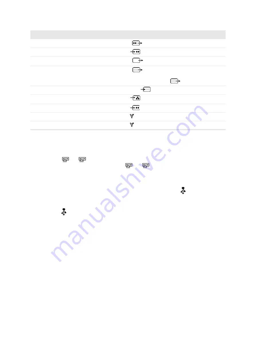
Table B-3. Overview of video documentation connections.
Documentation Trigger Connectors
In order to use the foot switch or
[
v
]
key to print the image on the screen, connect
1
or
2
to the trigger input of a video printer. For information about assigning
a
v
key or foot-switch pedal to
1
or
USB Devices
The CD writer built into the monitor base is connected to the
port at the top right
of the rear panel. For information about saving images on a CD, see Chapter 6,
“Documentation”.
port
A
is reserved for use with USB printers (black and white or color).
Images can be saved on a USB storage device (such as a USB flash drive) through
the USB port on the bottom left hand side of the monitor base. For information about
saving images, see Chapter 6, “Documentation”.
Connecting to a Surgical Rack
Using the optional Rack Docking System™, you can connect the scanner to a
surgical rack quickly, with just one connector. Then monitors in the operating room
can easily be used to view the ultrasound image. This is especially advantageous if
you are using the optional Picture-in-Picture (PiP) functionality. For further details
on PiP, See “The Video Window and Picture in Picture (PiP)” on page 82.
The scanner can easily be disconnected from the rack and used in another operating
room.
Video recorder
S-VHS Out
Video recorder
S-VHS In
For playback
Video monitor, B/W
Composite Out
Video monitor, Color
RGBS Out
Only one piece of external
equipment can be connected to
the
connector.
Video camera
RGBS In
Video camera
Composite In
Video camera
S-VHS In
Digital video camera
Digital video In/Out
Digital video recorder
Digital video In/Out
Equipment
Signal type
Connector
Comments
RGBS
RGBS
RGBS
1
or
2
1
or
2
Summary of Contents for Pro Focus 2202
Page 1: ...English BB1279 A June 2005 Pro Focus 2202 Extended User Guide ...
Page 14: ...14 ...
Page 15: ...Part 1 Basics ...
Page 16: ......
Page 32: ...32 Chapter 1 ...
Page 48: ...48 Chapter 2 ...
Page 49: ...Part 2 Working with the Image ...
Page 50: ......
Page 98: ...98 Chapter 5 ...
Page 117: ...Part 3 Imaging Modes ...
Page 118: ......
Page 136: ...136 Chapter 8 ...
Page 152: ...152 Chapter 10 ...
Page 164: ...164 Chapter 12 ...
Page 165: ...Part 4 Setting up and Maintaining Your System ...
Page 166: ......
Page 200: ...200 Chapter 13 ...
Page 208: ...208 Chapter 14 ...
Page 209: ...Part 5 Pro Packages ...
Page 210: ......
Page 288: ...288 Chapter 19 ...
Page 313: ...Part 6 Appendixes ...
Page 314: ......
Page 344: ...344 Appendix C ...


