background image

24

© 2019, ATEÏS, member of PAX ProAV Group

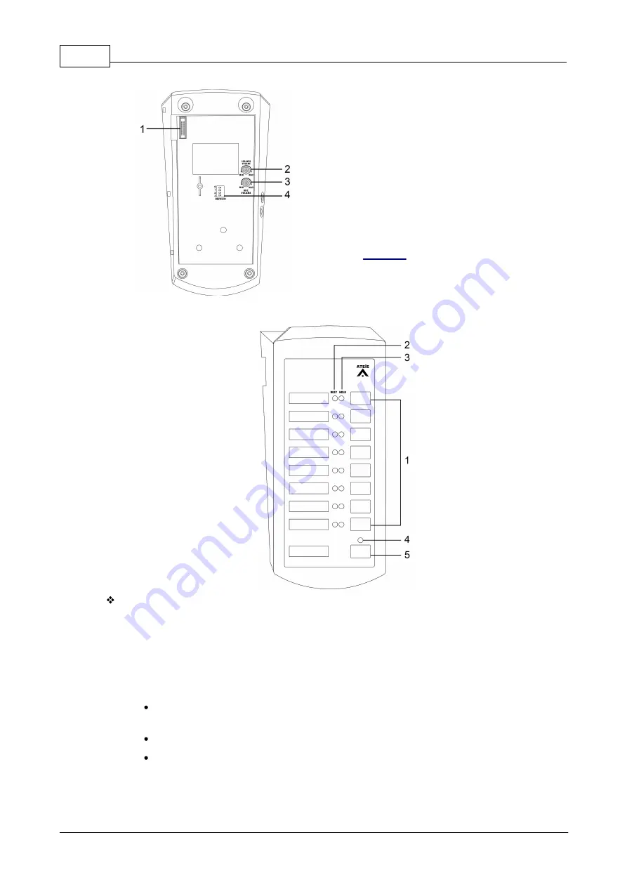
1. IDC connector:

For  transmitting  power  and  data  to  the  next
DPM-EVA/DPM-SPK unit via flat cable.

2. Speaker volume control.

3. Mic volume control.

4. Device ID:

Set  the DIP  switch to identify  the connection  of
multiple DPM-MAIN.  The DIP  switch is  followed
by the binary code with 4 digit. The ID cannot  be
repeated,  and  the  range  of  ID  is  from  1  to  31.
See 

Device ID

. 

2.5.1.2

DPM-KPD - additional 8+1 microphone keypad

Front panel:

1. Programmable button: 

There are eight  programmable  buttons  for  zone  paging,  event  triggering,  message  routing,
message play, level control etc..

2. Busy LED:

The LEDs will light up when the zones are occupied by the other audio sources.

Green LED: The paging zones are occupied by  the other audio sources  which have lower
priority, and is able to page.

Continuous blink in green: The selected zones on DPM are under paging now.

Red LED:  The paging zones  are occupied by  the other audio sources  which  have  higher
priority, and is not able to page. 

3. Hold LED:

Summary of Contents for BOUTIQUE BTQ-VM425W1

Page 1: ... 2019 ATEÏS member of PAX ProAV Group Revision History v1 13 BOUTIQUE TM Compact and Self Amplified Public Address and Voice Alarm System User Manual User Manual ...

Page 2: ...PM T5 DPM T5F touchpanel paging mic 2 5 2 28 Front panel 2 5 2 1 29 Side rear panel 2 5 2 2 29 CD 8DF CD 16DF wallmount paging mic 2 5 3 30 Front panel 2 5 3 1 31 CD T5DF wallmount touchpanel paging mic 2 5 4 32 Front panel 2 5 4 1 33 2 6 2 6 Accessories 33 DNM2 ETH digital ambient noise sensing mic Ethernet 2 6 1 33 DGL MIC flush ceiling mount microphone 2 6 2 33 DGL MIC front panel rear panel 2 ...

Page 3: ...AC 5 RAC 8 53 3 18 3 18 DNM2 ETH 53 Installation notice 3 18 1 4 Hardware configuration operation 55 55 4 1 4 1 BTQ VM LCD panel 55 Setup wizard 4 1 1 55 New setup 4 1 1 1 55 Step 1 language 4 1 1 1 55 Step 2 number of main and secondary units ID 4 1 1 1 57 Step 3 number of remotes 4 1 1 1 57 Step 4 power amplifier s sharing 4 1 1 1 58 Step 5 dummy load capacitor 4 1 1 1 59 Step 6 monitoring 4 1 1...

Page 4: ... level 5 1 3 1 86 LCD panel web browser 5 1 3 1 87 Add user 5 1 3 2 88 Modify user 5 1 3 3 88 Delete user 5 1 3 4 88 Login logout 5 1 3 5 88 Synchronize icon 5 1 4 88 Configuration file upload download 5 1 5 89 System 5 1 6 89 Device management 5 1 6 1 89 System size 5 1 6 1 89 Hide units 5 1 6 1 89 Add delete remotes 5 1 6 1 90 Add a DPM MAIN DPM T5 CD 8DF CD 16DF CD T5DF 5 1 6 1 3 91 Add a DNM2 ...

Page 5: ... 8 2 113 Edit evac alarm event 5 1 8 2 1 115 Normal logic inputs 5 1 8 2 116 RAC calibration 5 1 8 2 117 Relay outputs 5 1 8 2 117 Paging 5 1 8 3 118 Add singular type 5 1 8 3 119 MSG TEST ALERT EVAC 5 1 8 3 1 119 FIREMAN 5 1 8 3 1 120 MIC 5 1 8 3 1 121 CD AUX 5 1 8 3 1 121 MEMORY 5 1 8 3 1 121 INTERNET 5 1 8 3 1 122 VOIP 5 1 8 3 1 122 Add integration type 5 1 8 3 124 DPM T5 Record Listen Paging 5...

Page 6: ...essage 5 1 12 1 1 146 Compoments 5 1 12 1 146 Equalizer 5 1 12 1 2 147 Dynamic 5 1 12 1 2 149 Internal external CH output 5 1 12 1 2 149 Ambient noise sensing microphone static dynamic 5 1 12 1 2 150 Static 5 1 12 1 2 151 Dynamic 5 1 12 1 2 152 Calibration 5 1 12 1 2 152 Stream out 5 1 12 1 153 Parameter range 5 1 12 2 6 Maintenance 154 7 Fault lists troubleshooting 155 8 Technical data 162 162 8 ...

Page 7: ...7 Contents 2019 ATEÏS member of PAX ProAV Group ...

Page 8: ...from the device Otherwise fire or electrical shock may result Connect the power cord only to an AC outlet of the type stated in this manual or as marked on the unit Otherwise fire and electrical shock hazard results When disconnecting the power cord from an AC outlet always grab the plug Never pull the cord A damaged power cord is a potential risk of fire and electrical shock hazard Avoid touching...

Page 9: ...event the unit from falling down and causing personal injury and or property damage avoid installing or mounting the unit in unstable locations Leave enough space above and below the unit to provide good ventilation of the device If the airflow is not adequate the device will heat up inside and may cause a fire Operate the device in an environment with a free air temperature of between 5 C 55 C 23...

Page 10: ... with 250W or 500W high efficiency Class D amplifier built in Varies functions such as system easy setup function providing installer an ease of installation and configuration directly from LCD front panel The BOUTIQUE system expands from a single controller capable of as little as 4 zones to a larger networked system of up to 16 384 zones making the system suitable for a wide variety of applicati...

Page 11: ... installed on monitored speaker lines without loopback cabling This feature is supported only for the model with EOL Driver such as BTQ VMD825 BTQ VMD450 in the model number D means EOL Driver 2 2 1 Front panel 1 Fireman microphone U shape bracket A fully monitored microphone is designed for EVAC paging The paging button supports both press to talk and lock to talk mode The talk mode can be set vi...

Page 12: ...on to manually play the alert message to selected or pre defined zones and a LED will light up as long as the button is pushed 15 All Call Cancel button A button to select all the zones in the entire BOUTIQUE system or reset the current zone selection 16 Route button A button to manually route the selected music source CD Tuner Aux USB Internet to selected or pre defined zones 17 Select button A b...

Page 13: ...tput of external amplifier 3 A B line zone outputs The BTQ VM4 has 4 zones and BTQ VM8 has 8 zones Connect the loudspeakers to the zone outputs Each zone output is consisted of two loudspeaker line outputs The open short and bad impedance faults can be detected by system for both speaker lines The controller is capable of handling 1000W speaker load per zone 2000W max per unit 4 Relay control outp...

Page 14: ...ing consoles or accessories to be connected to BTQ VM4 8 SG SL unit Each remote port on BTQ VM4 8 controller and BTQ SL8 SG8 unit can address up to 8 DPM MAIN remote consoles in daisy chain or up to 16 units in redundant loop using 2 ports Max remotes per BTQ SL8 8 Max remotes per BTQ VM4 8 16 Max distance between digi link remote units 250m shielded RJ45 connector STP CAT5 6 11 USB 2 0 interface ...

Page 15: ...is not present 22 Battery backup Connect the 48VDC battery charger for battery backup 23 Ground GND socket 2 3 BTQ VM4W VM8W wallmount PAVA controller The BTQ VM4W VM8W is a wallmount controller with 250W or 500W Class D amplifier built in integrated battery charging unit for secured battery backup and power sharing All components contain within one heavy duty metal housing with a lockable cover V...

Page 16: ...825W1 BTQ VM850W1 BTQ VM425W2 BTQ VM825W2 BTQ VM825W2 BTQ VM850W2 The W1 indicates as 1 optional amp is included and W2 indicates as 2 optional amp are included 2 3 1 Front panel BTQ VM4W VM8W housing with alockable cover The front panel of BTQ VM4W VM8W controller is also identical to BTQ VM4 VM8 controller see BTQ VM4 VMW Front Panel ...

Page 17: ...ontroller will use AC mains first and switch to DC power if the AC mains is not present Make sure to unplug the AC mains power before plugging the 48VDC battery backup power The rest of interface of BTQ VM4W VM8W controller is also identical to BTQ VM4 VM8 controller see BTQ VM4 VMW Rear Panel 2 4 BTQ SG8 BTQ SL8 PAVA secondary global local unit To increase the number of zones EVAC inputs logic in...

Page 18: ...BTQ SGD8 and BTQ SLD8 in the model number D means EOL Driver 2 4 1 Front panel BTQ SG8 Global Net BTQ SL8 Local Link 1 Power LED This green LED lights up if the BTQ SL8 SG8 is connected to the power adapter or 24VDC input battery supply 2 5 VACIE indicator LED There are eight rows of 3 LEDs that show in real time mode of the status of zone 2 EVAC LED The red LED lights up if the zone is in evacuat...

Page 19: ...rammed for phase evacuation and to monitor the external contact Each channel supports 3 modes Monitored contact mode The system can monitor the evac input and detect faults 4 status on off open and short Disable The cables which connect to evacuation input will not be monitored faults will not be detected Voltage mode Trigger the input by a voltage change OPEN CLOSE with an external 24VDC source p...

Page 20: ...bal network redundant loops is used to link the BTQ VM4 8 controller to the next connected BTQ VM4 8 or BTQ SG8 units It supports both RJ45 plug and fiber optics o Max global net units 64 o Max distance between global net units 100m STP CAT5 6 2 km multi mode ber optic and 20 km single mode ber optic Digi link port RJ45 The local digi link network is used to link the BTQ VM4 8 controller and BTQ S...

Page 21: ...aging console the DPM KPD is an expansion keypad used to expand the DPM MAIN and the DPM EVA is a monitoring speaker pad with an EVAC button and 5 programmable buttons Each remote port on BTQ VM SL SG can address up to 8 DPM MAIN remote consoles in daisy chain or up to 16 units in redundant loop using 2 ports Each DPM MAIN can attach one DPM EVA and up to 16 DPM MAIN with DPM EVA KPD are linked by...

Page 22: ... button There are eight programmable buttons for zone paging event triggering message routing message play level control etc 4 Busy LED The LEDs will light up when the zones are occupied by the other audio sources Green LED The paging zones are occupied by the other audio sources which have lower priority and is able to page Continuous blink in green The selected zones on DPM are under paging now ...

Page 23: ...r priority and the Busy LED will light up in red Side panel 1 Headphone jack output External headphone 3 5mm jack output 2 Microphone jack input External microphone 3 5mm jack input When the external microphone is connected the gooseneck mic on DPM MAIN will be disable when external headphone is connected the loudspeaker on DPM EVA will also be disable Rear panel Remote console sockets Connect the...

Page 24: ...5 1 2 DPM KPD additional 8 1 microphone keypad Front panel 1 Programmable button There are eight programmable buttons for zone paging event triggering message routing message play level control etc 2 Busy LED The LEDs will light up when the zones are occupied by the other audio sources Green LED The paging zones are occupied by the other audio sources which have lower priority and is able to page ...

Page 25: ... blue when the the event is triggered 4 All Release LED The LED will light up off if all the zones are selected deselected 5 All Release button This button is used for select deselect all zones Bottom panel 1 IDC cable The connector is used for transmitting power and data to the next DPM unit via flat cable 2 5 1 3 DPM EVA EVAC unit with speaker and extra buttons Front panel ...

Page 26: ...rogrammable buttons for zone paging event triggering message routing message play level control etc 6 Busy LED The LEDs will light up when the zones are occupied by the other audio sources Green LED The paging zones are occupied by the other audio sources which have lower priority and is able to page Continuous blink in green The selected zones on DPM are under paging now Red LED The paging zones ...

Page 27: ...communication cable length between the controller secondary units and paging consoles is 250M 820 ft via STP CAT5 6 cable with shielded RJ45 connector The DPM T5 DPM T5F is equipped with a 3 5mm phone jack mic input and a speaker output for the connection of external headset Both DPM T5 and DPM T5F have a mini USB port for PC Laptop connection making the far end device using Skype QQ WhatsApp etc ...

Page 28: ...ound tone as warning 3 Touch screen panel A 5 LCD touch screen and each pages on the panel can be pre programmed to zone paging trigger events etc See DPM T5 DPM T5F CD T5DF LCD panel for details 4 EVAC LED This LED lights up in red when system is under the evacuation paging 5 Fault LED This LED lights up in yellow when one or more system faults are detected 6 Power LED This LED lights up in green...

Page 29: ...phone DPM T5 only 3 5mm 1 8 inch phone jack female for external headphone Remote console sockets Connect the DPM T5 DPM T5F to BTQ VM SL SG or cascade the next DPM T5 DPM T5F DPM MAIN CD 8DF 16DF T5DF DGL MIC via this RJ45 redundant sockets A and B port If the power supply of DPM T5 DPM T5F is insufficient it needs to be connected to a DLR01 digital loop repeater for expanding the distance to 250M...

Page 30: ...ing recording message routing message playing button etc and can be configured via web browser In addition it is equipped with a fireman microphone and an evacuation button Up to 8 CD 8DF CD 16DF can be connected to a remote port of BTQ VM SG SL via daisy chain and up to 16 in redundant loop The maximum communication cable length between the BTQ VM SG SL and remote units is 250M 820 ft via STP CAT...

Page 31: ...aging zones are occupied by the other audio sources which has higher priority and is not able to page 5 Hold LED The LEDs will light up blue when the zones zone group are selected and allowed to distribute The LEDs will blink once in blue when the the event is triggered 6 Evacuation button Once this button is pushed the system will enter to emergency state The red LED will light up and play route ...

Page 32: ... microphone U shape bracket A fully monitored microphone is designed for EVAC paging The paging button supports both press to talk and lock to talk mode The talk mode can be set via web browser 2 Monitoring speaker This built in speaker is to monitor the zone audio including message and BGM When a fault is detected in the system it will generate a buzzer sound tone as warning 3 Evacuation button O...

Page 33: ...IC enhances the ability to detect the background noise and automatically adjusts the output level of loudspeaker to achieve the optimal intelligibility of sound The DGL MIC is connected to standard RJ45 connector connected to remote console port of BTQ VM4 VM8 the DGL MIC can connect with up to 250m via STP CAT5 6 cable with shielded RJ45 connector Click DNM2 ETH installation to see more details 2...

Page 34: ...tes in a redundant loop daisy chain wiring is not strong enough the DLR01 can extend the distance of remotes 250m longer In addition the DLR01 is equipped with the 24VDC external power input providing local power to the remotes 2 6 3 1 Top panel 1 Power NEXT LED The 24VDC power output LED 2 Power LED Light up when the DLR01 is powered 3 EXT power LED The 24VDC power input LED 2 6 3 2 Side panel 1 ...

Page 35: ...rammed via web browser The RAC 5 8 is available for US and EU type and powered by 24VDC RAC 5 RAC 8 RAC 5 RAC 8 EU Type US Type See RAC 5 RAC 8 wiring connection 2 6 5 VAT volume attenuator VAT 35E 120E 200E VAT 35U 120U 200U EU Type US Type The VAT is a volume attenuator equipped with a 5 step attenuation plus a OFF step it offers precise level control and excellent frequency response to the spea...

Page 36: ...nged after adjusting the volume on VAT volume attenuators Furthermore for branching the speaker line wiring a cut of partial branching may not change the overall impedance that obviously Therefore the VA EOL is the only solution which can adapt the changing impedance and detect open or short circuit for each branch By installing the VA EOL at the end of speaker lines the system can indicate which ...

Page 37: ...can be connected under the ATEÏS BOUTIQUE global network Thanks to the benefits of ATEÏS redundant network algorithm the redundant network loop on BTQ VM SG units makes sure the system be continually functional when occurs unexpected cable disconnection The installation of NET2 RR card RJ45 to RJ45 port is suitable with a maximum distance of 100m in global network For installation with longer dist...

Page 38: ...plies or power amplifiers Installing a BTQ SL8 SG8 secondary unit is similar to installing a BTQ VM4 VM8 controller except the secondary units are installed in 19 inch 1U rack mounting 3 3 BTQ VM4W VM8W mounting This mounting and connection must be carried out in accordance with all applicable standards and regulations by an electrically skilled person Danger Electrical shock The installation of B...

Page 39: ... 22 kg without 4 batteries Depending on the used battery capacity and the resulting weight of the batteries please make sure the drywall have sufficient strength to support the entire weight of this load 3 Drive the nails into the wall stud for fixing the BTQ VM4W VM8W on wall see the picture as below 3 3 2 BTQ VM4W VM8W wiring 1 Observe the position of the necessary cables including L wire N Neut...

Page 40: ... G Ground wire on the AC input terminal is sufficient for the connection of BTQ VM4W VM8W 4 Connect the L wire and N Neutral wire on the AC input terminal to the AC L AC N power wires of BTQ VM4W VM8W euroblock connector 5 Connect the G Ground wire on BTQ VM4W VM8W see the picture as below ...

Page 41: ... Danger Electrical shock The wiring of BTQ VM4W VM8W must only be operated when the AC power supply is closed 6 Use other cable entries for connecting the rest of essential signalling cables such as audio cables Ethernet cables etc to BTQ VM4W VM8W see the picture as below ...

Page 42: ...ber of PAX ProAV Group 3 3 3 Mounting the batteries in BTQ VM4W VM8W 1 Mount the four 12Ah batteries 10Ah to 30 Ah in series inside the BTQ VM4W VM8W And use cable ties for fixing the batteries see the picture as below ...

Page 43: ...tteries must only be operated when the AC power supply is closed Before powered on the BTQ VM4W VM8W please use the electric meter to measure the battery voltage 43 2VDC 60VDC total The BTQ VM4W VM8W has two terminals PBAT DGND for connecting to the batteries 1 Connect the DGND terminal to the terminal of the first battery 2 Connect the PBAT terminal to the terminal of the last battery 3 Connect t...

Page 44: ...it Use STP CAT5 6 cable with shielded RJ45 connector to connect a BTQ SL8 secondary unit to BTQ VM4 8 controller Up to 31 BTQ SL8 units can be connected under the local digi link network To identify the connection among the secondary units each secondary unit has an unique ID And the ID must be set orderly based on the Digi link connection For example if the ID of BTQ ...

Page 45: ...an address up to 8 DPM MAIN consoles The maximum communication cable length is 250M 820 ft between the controller secondary unit and DPM console DPM and DPM via STP CAT5 6 cable with shielded RJ45 connector subjects to the power supply is sufficient Multiple DPM consoles can be wired in a daisy chain or redundant loop using 2 ports Each DPM MAIN can attach one DPM EVA and up to 15 DPM KPD can link...

Page 46: ... DPM T5F CD 8DF CD 16DF CD T5DF Connection When connects more than 2 DPM T5 DPM T5F CD 8DF CD 16DF CD T5DF units they can be wired in a daisy chain or as a redundant loop The installation is similar to installing a DPM see Redundant loop daisy chain wiring 3 7 DLR01 The DLR01 is a digital loop repeater with power injector it can extend the wiring distances of peripherals such as DPM MAIN EVA KPD D...

Page 47: ...nal power amplifier The BTQ VM4 8 controllers have an internal 250W or 500W amplifier built in For system power sharing and or backup connect a second power amplifier DPA or BPA externally The BTQ SL8 secondary unit can share power amplifier from BTQ VM4 8 controller secondary units or connect to an external power amplifier Both of the controller and secondary unit are capable to handle the power ...

Page 48: ...ry unit see web configuration settings controllers secondary units 3 9 Battery charger power sharing For DC battery backup power sharing connect the battery charger to BTQ VM4 8 controller and external power amplifier as the picture below The example below is using the BCU 4830A BCU 4875A battery charger and BPA or DPA power amplifier from ATEÏS ...

Page 49: ...etup Wizard on front LCD panel of BTQ VM4 8 or web browser see Setup Wizard Net Setup Step 5 Dummy Load Capacitor and it will automatically calculate the total speaker line load watt 3 After completed the Step 5 of Setup Wizard follow the recommended data for the DIP switch of VA DLC displayed on LCD panel of controller or web browser and set ON position on the corresponding DIP switch of VA DLC 4...

Page 50: ...tenuator is capable to increase decrease the volume of background music remotely during BGM broadcasting and the volume will not be attenuated during EVAC message broadcasting In addition by installing the VA EOL at the end of speaker lines the system can quickly indicate which speaker line is open short circuit in every branch By the case of A B zone wiring and branching it needs to add the VA EO...

Page 51: ...A EOL must have unique ID set the 8 bit DIP switch for each VA EOL 3 13 Logic inputs The logic control Inputs are designed to work with simple contact or button see the wiring connection as below See the wiring connection between RAC 5 RAC 8 and BTQ VM4 8 from Hardware installation connection RAC 5 RAC 8 ...

Page 52: ...hange OPEN CLOSE with an external 24VDC source provided by external devices The cable is not monitored in this mode 3 15 Mic Line input with VOX XLR The BTQ VM4 VM8 controller has 1 Mic Line balanced XLR input with voice activated VOX When connecting the MIC Line input please switch ON on VOX setting and adjust the mic volume by the gain knob The BTQ VM4 VM8 also provides 48VDC phantom power for M...

Page 53: ...8 DNM2 ETH devices can connect to each BOUTIQUE local network and up to 256 DNM2 ETH devices can connect to a BOUTIQUE system 8 DNM2 ETH x 32 local networks When the loudspeakers are placed in a big area such as railway station hall loudspeakers are put in different locations which requires to install multiple DNM2 ETH units for having clear enough sound for each position of the area Then users ne...

Page 54: ...that if the DNM2 ETH is installed at a quiet place and the level of broadcasting is too small for the loud side users can divide the zone to several area and one DNM2 ETH for one divided area 4 Also users can set the gain value based on the loudest noise which is detected by DNM2 ETH so that every section in the same area can hear the broadcasting clearly See DNM2 ETH web configuration to set the ...

Page 55: ...uration control and system status display After completed the hardware wiring the LCD panel will activate automatically once it is powered Press the touch panel to start the system setup 1 New Setup Setup Wizard 2 Replace replace the broken main controller with the new one 4 1 1 1 New setup 4 1 1 1 1 Step 1 language Press on touch panel to set the language Press OK 4 1 1 1 2 Step 2 number of main ...

Page 56: ... Edit to change the number of VM4 VM8 VM8W1 VM8W2 and SG units 2 Press Save to apply settings Set the ID of BTQ VM4 VM8 VM8W1 VM8W2 controller and SG unit 1 Select the unit and press Edit to change its ID 2 Press Save to apply settings Set the number of secondary local units SL 1 Select VM8 SL block via button and press Edit to change the number of SL units 2 Press Save to apply settings 3 Press S...

Page 57: ...in controller and external amplifier can be shared among the main controllers and secondary local units Single Amplifier Dual Channel Amplifier The internal amplifier in the main controller can share power amplifier with secondary local unit s to expand speaker zones Except the internal amplifier in the main controller it is possible to have second amplifier externally for system power sharing and...

Page 58: ... remove the unit for power sharing in the amplifier 3 Repeat 2 to add delete more units 4 Press Save to apply settings Set CH1 Amp 1 power 1 Press to change the power wattage of which Int Ext amplifier channel and Save the settings 2 Press for the CH1 Amp2 settings and repeat the same procedure for other amplifier s settings 3 Press Step 5 4 1 1 1 5 Step 5 dummy load capacitor Calculate dummy load...

Page 59: ... the indicated number to ON position on the DIP switch 3 Press Next 4 1 1 1 6 Step 6 monitoring Set the monitor tolerance of speaker line impedance and power amplifier 1 Press Next to apply the preset tolerance impedance and amplifier gain Or press Edit to change the tolerance of percentage 2 Press Save to apply settings Press Next to get monitor reference Press Ready and Activate to enter the men...

Page 60: ...ig file from USB to replace figure 1 If the USB flash drive is not connected the system will display the alert window figure 2 2 If not using the file from USB flash drive click Skip to skip the step figure 1 figure 2 4 1 1 2 1 Step 1 net ID Select the netcard ID of the new BTQ VM4 VM8 controller used to replace the broken one Click Next to apply the setting 4 1 1 2 2 Step 2 backup read The config...

Page 61: ...AV Group 1 Select the config file and press OK 2 Press Yes to apply the config file to the system 3 Press OK to enter the menu window 4 1 2 LCD menu 4 1 2 1 Mic Line FMM Recovery Log List Fault List Logout Login Mic Line Adjust the volume or mute unmute the Mic Line ...

Page 62: ...ault configuration for synchronization to the broken one s Log list Display the content of log list Fault list Display the list of fault occurrences Logout Click to logout In case of multi users with different level you can logout from the current user session in order to login in an other one Login Login the LCD display by entering the username and password ...

Page 63: ...f amplifier and speaker line again System reset Clean the system fault list the System Fault LED will light off as well Paging reset Cancel all the paging in the system Lamp test Test the lighting of LED LCD display relay output of all the connected controllers and secondary units o LED Light on off the LED o LCD display Change the color of display in red green blue white black ...

Page 64: ...ubmask DNS DHCP MAC Default Setting BTQ VM BTQ SG8 IP address 192 168 102 125 192 168 102 124 Subnet Mask 255 255 252 0 255 255 252 0 Gateway 192 168 100 254 192 168 100 254 DNS 0 0 0 0 0 0 0 0 When changing the Ethernet settings the BOUTIQUE system needs to reboot Net ID Set the ID of BTQ VM4 8 controller through the ATEÏS global net Brightness Set the brightness of LCD display Enter security Cho...

Page 65: ...in speaker of BTQ VM4 8 controller when a fault is detected FP saver Skip to product map Set the time to let the LCD panel return to the welcome page automatically Turn off the backlight Set the time to turn off the LCD panel of main controller automatically To activate the LCD panel again users can press any button on the front panel of main controller Backup Backup read The config files will be ...

Page 66: ...from the connected USB flash drive to proceed routing Multiple message files can be selected and routed max 999 files Please make sure the USB flash drive is connected on the main controller SEL Display the number of files which user has chosen Press this button to select deselect all the listed files Battery capacity Display the total battery capacity AH charging current A DC maximum output curre...

Page 67: ...l All the zone buttons on the LCD panel of DPM T5 DPM T5F CD T5DF can be configured via web browser and used for displaying and operation Before operating the DPM T5 DPM T5F CD T5DF please note the settings of zone buttons such as pre post announcement chime talk mode lock to talk press to talk priority button name event function etc needs to be configured on Configuration Integration Paging first...

Page 68: ...nction 1 Monitor Here you can monitor the paging zones and audio sources of BOUTIQUE from the built in speaker of DPM T5 DPM T5F CD T5DF see Monitor page 2 Message Play the audio messages to the selected zones see Message page 3 Routing Here you can audio routing to the selected zones see Routing page 4 Fault Display all the faults detected by BOUTIQUE units see Fault page 5 Setting Press to enter...

Page 69: ... zone button is paging or playing the messages from DPM T5 DPM T5F CD T5DF When this unselected button selected button is an event button on DPM T5 DPM T5F CD T5DF 4 2 2 Chime talk To page to the selected zones with a chime tone see the steps of Chime Paging example as below 1 First upload the chime files on web browser message management 2 Choose the pre chime file and post chime file on web brow...

Page 70: ...from the built in speaker of DPM T5 DPM T5F CD T5DF see the steps as below 1 Choose a BOUTIQUE unit 2 Choose Auto or Normal mode Auto Press Auto to automatically monitor the audio source which pages to the selected zones Normal Press Normal button and manually monitor the source which pages to the selected zones 3 Press Monitor button to start the Monitor function 4 To cancel the Monitor function ...

Page 71: ...ons you wish to be played the message files see as below If users wish to play the messages to all the zones press Select All Zone button 4 To preview the audio messages press Listen button 5 Press Play Stop button to start playing messages to zones 6 To cancel this message playing press Play Stop button again 4 2 6 Routing Select a audio input source of BOUTIQUE and route this audio source to the...

Page 72: ...er selected the zone buttons press Route button to start routing audio source to zones 5 Press Route Modify button if users wish to add or remove the zone buttons from the current routing see Modify Zone 6 To cancel this audio routing press Stop button 4 2 7 Fault When a fault has detected this page will show all the fault details Press the selected fault it will show the fault detail See Fault Li...

Page 73: ...DPM T5 DPM T5F CD T5DF can be connected to BTQ SL8 and 16 on BTQ VM4 VM8 SG8 Please note the remote ID you set here needs to be the same you set on the web browser otherwise the DPM T5 DPM T5F CD T5DF will display in offline status on web browser Device Management 1 Mic calibration To let the detection of gooseneck mic be more accurate users can proceed this function o First plug out the gooseneck...

Page 74: ...ystem Device Management Add Remote Stack Paging see the example of Stack Paging as below 1 Select the zone buttons you wish to paging by DPM T5 DPM T5F CD T5DF 2 Then press Talk button to proceed the Stack Paging 3 Press Start to record 4 Once finished the recording press Stop Press Cancel to cancel the stack paging and go back to the zone paging page 5 Press Listen to use the loudspeaker of DPM T...

Page 75: ...The key buttons on DPM MAIN DPM EVA DPM KPD CD 8DF CD 16DF and the keys on the LCD panel of DPM T5 DPM T5F CD T5DF can be configured with various function including zone paging chime paging record preview the recorded file delete level adjustment etc Please ow tosee the following steps bel do the key configuration 1 Please check if the hardware wiring between the DPM or DPM T5 and the BTQ VM4 VM8 ...

Page 76: ... Chime 9 None DPM T5 DPM T5F CD T5DF Key Function 1 Zone 2 Event 3 Wave Record 4 Wave Listen 5 Wave Delete 6 Wave Paging 7 Wave Level 8 Jump Page 9 Press to Talk 10 Press to Talk with Chime 11 None 5 To know about the key functions and other advanced settings of DPM and DPM T5 DPM T5F CD T5DF see Add integration type for details 4 4 Device ID The BTQ SL8 BTQ SG8 secondary units and DPM MAIN paging...

Page 77: ... SL8 2 After the ID setting and the rest of the device hardware wiring are completed go to Web Browser Device Management System Size to build a BOUTIQUE system by adding the number of controller secondary units in the same group based on the hardware wiring 3 Then go to Device Management to check if all the BOUTIQUE units are online To identify the connection among the secondary units each seconda...

Page 78: ...Source button lights off 3 Press the ROUTE button again to cancel the routing Zone attenuators volume knobs When using a BGM source CD AUX USB etc to paging to zones and the Evacuation option on this source is disable then users can change the volume of corresponding zones to the desired attenuation level from the front panel of controller The attenuators offer 6 attenuation positions 0 3 6 9 12 1...

Page 79: ... message playing it can be done by manual zone selection or with pre defined zone on web browser Play message to pre define zones 1 Press ALERT button and the Paging NOW message will be displayed on LCD panel and press OK 2 Then the message will be played in the pre defined zone s Play message with manual zones selection 1 First press the zone buttons to select the zones which you wish the message...

Page 80: ...ophone please read Paging Mode Fireman microphone Start a call with pre define zones Press the fireman microphone to start calling in the pre defined zones the EVAC LEDs with the corresponded zones will light up see the evac setting of EVAC LED from Singular type paging The fireman mic paging can be defined as evac call and general broadcasting via web browser Start a call with manual zones select...

Page 81: ...oken main controller with the new one proceed the Replace Setup to configure and synchronize the process again only with the broken device 5 1 1 1 New setup 5 1 1 1 1 Step 1 language 1 Select the drop down box to choose the language 2 Press Next to move to Step 2 number of main and secondary unit settings 5 1 1 1 2 Step 2 number of main and secondary unit Set the number of main controller and seco...

Page 82: ...plifier from the main controller and the external power amplifier The internal amplifier can also share its power with other secondary unit An external amplifier can also be connected for spare switching Therefore you can define which amplifier in the same group in order to share its power 1 Set the group based on the number of local net the BOUTIQUE system has The Group 1 indicates the amplifiers...

Page 83: ... dummy load capacitor in the end of speaker line for each sub zone 2 Set the indicated number to ON position on the DIP switch 3 Click Next to move to Step 6 Monitoring settings Printing Setting of dummy load capacitance Tick Graphic checkbox and Text checkbox to display the DLC setting for printing 5 1 1 1 6 Step 6 Monitoring Set the monitor tolerance of speaker line impedance and power amplifier...

Page 84: ...w BTQ VM4 VM8 controller used to replace the broken one 2 Click Next to move to Step 2 backup read recovery settings Click Skip if users have already set the netcard ID of the new BTQ VM4 VM8 controller from the LCD panel of BTQ VM4 VM8 5 1 1 2 2 Step 2 backpup read recovery Backup read Use the config file from the USB flash drive which is connected on the new BTQ VM4 VM8 unit 1 Select the config ...

Page 85: ...webpages of the BOUTIQUE system after connecting Default Setting BTQ VM BTQ SG8 IP address 192 168 102 125 192 168 102 124 Subnet Mask 255 255 252 0 255 255 252 0 Gateway 192 168 100 254 192 168 100 254 DNS 0 0 0 0 0 0 0 0 IP address Assign the IP address to the BOUTIQUE device and change the IP address of device go to Machine Settings IP SIP settings The BOUTIQUE streaming can be done using a SIP...

Page 86: ...DSP adjustment read log fault list etc on web page o To enter level 1 a password is needed Level 2 is defined to be for person having a specific responsibility for safety Level 2 has all the authority of level 1 o To enter level 2 a password is needed Level 3 is for specific maintenance operator and trained persons Level 3 has all the authority of level 2 o To enter level 3 a password is needed Le...

Page 87: ...ge Management Playlists 2 Scheduler 2 Evac 2 Paging 2 Event 2 Monitor 2 Device management 3 Update operation 3 Skin file operation 3 Table synchronization 3 Machine Setting IP SIP RS232 Port Third Party Controls Power Saving 3 Configuration File 3 Wizard Setting 3 User Manager operation 4 5 1 3 2 Add user 1 Enter the User ID and the password The passwords must contain at least one number or letter...

Page 88: ...quest you to enter your password repeat the same procedure to enter the password Login from ATEÏS web browser 1 Enter a valid user ID and password 2 To logout go to the right top section and click Logout Click if users forget the password but you need to enter the account first 5 1 4 Synchronize icon The Synchronization icon on the right top section of the webpage indicates whether the system conf...

Page 89: ...5 1 6 1 1 System size Allow to quickly build a BOUTIQUE system by adding the number of main controller secondary units in the same group the setting can be dynamically modified and adapted to the current setting The max number of group is 64 5 1 6 1 2 Hide units Click the checkbox to proceed the Hide Secondary Unit and Hide Remote Devices option 5 1 6 1 3 Add delete remotes Add Remote button Add a...

Page 90: ...just the gain of the source automatically by setting a target level Target gain The level will be increased up to target level when audio level is above the threshold value Max gain The maximum gain of AGC function This function keeps a natural and dynamic audio Response time If the audio input level is continually greater than Noise threshold for this period of time the gain operation will be act...

Page 91: ... the stack paging does not play within the Wait Time it will be automatically canceled o Paging stacking Pre record the paging message and play it using the built in speaker of DPM T5 CD T5DF for confirmation first Reset selection after paging Enable disable to auto deselect the zones after the paging ends 5 1 6 1 3 2 Add a DNM2 ETH Name The name of DNM2 ETH Device The type of remote Choose DNM2 E...

Page 92: ...secondary units Moreover an external power amplifier can also be connected for backup Therefore you can define which amplifier in the same group in order to share its power 1 Go to System Device Management Setting controller or secondary unit 2 Click Setting button on Device Management to enter the setting window of controller secondary unit see the picture below ID The ID of BTQ VM4 VM8 VM8W1 VM8...

Page 93: ...ler can share power amplifier with secondary local unit s Equipment o One BTQ VM850 main controller unit o One BTQ SL8 secondary unit Web browser setting Type AMP1 AMP1 Power AMP2 AMP2 Power VM8 with built in amp Int 500 SL 1 Int Connection 5 1 6 1 4 2 Application2 medium scale type This application is used for multiple zones such as shopping mall or several floors building which require to use ad...

Page 94: ...example as airport the zone of Terminal 1 requires to connect two amplifiers internal amp and external amp zones of Terminal 2 requires another two amplifiers and zone of Gate01 030 requires two amplifiers Equipment o One BTQ VM850 main controller unit o Two BTQ SL8 secondary units o Five external power amplifiers Web browser setting Type AMP1 AMP1 Power AMP2 AMP2 Power VM8 with built in amp Int 1...

Page 95: ... work with a selected noise sensing mic group Priority If multiple zones are under paging from one source use the priority to decide which group to detect the background ambient noise and auto adjust the output level The 1 is the highest priority o If the priority among the groups is the same the small number of the group will be in higher priority For example the Group 1 has higher priority than ...

Page 96: ...t Static If the DNM2 ETH is a static type it will use the minimum level of ambient noise which has detected by DNM2 ETH units in the beginning paging and use the gain vale to adjust the level of speaker output Select all Click to select all the listed DNM2 ETH units or a DGL MIC unit Add to group Tick the checkbox to add the DNM2 ETH DGL MIC into the selected group Please note when using the DGL M...

Page 97: ...n of Evacuation the system will calculate the the power consumption and recommend capacity of battery Example If the system is set as the following table When the system enters to emergency state the siren sound will start buzzing for 5 seconds and silence after then the EVAC message for emergency evacuation will be played This evacuation process will continue till it passes 30 minutes siren durat...

Page 98: ... Reboot button Remember to click Reboot button after updated the firmware so that it will apply to the BOUTIQUE device The checkboxes on the top section allows users to filter multiple options and devices main controller secondary unit console successful update failure update and will be listed in the table according the filter option 5 1 6 4 2 Language Update the custom language file lang and the...

Page 99: ...controller and DPM T5 CD T5DF to the latest version The GUI update is similar to a firmware update see Update Firmware 5 1 6 5 Table synchronization When the configuration on BOUTIQUE devices have been changed this table will display either Synchronize or Asynchrone on device status Please note the synchronization function is applicable to the system which has more than one BTQ VM4 8 controllers a...

Page 100: ...ion message on front panel again USB backup Enable disable to auto backup the config file message files language file and font files ttf to the connected USB flash drive Ethernet monitor When this option is enabled and the Ethernet cable on BTQ VM BTQ SG8 is not fully connected or loose the system will detect and recognize it as a fault 5 1 7 1 2 FP saver Skip to product map Set the idle time to l...

Page 101: ...4 SIP DTMF reminder Enable to let the zones which has assigned in the DTMF keys to hear the sound of DTMF tones from PPM IT5 or IP phone See how to create DTMF intercom call Auto answer Set how many call rings before picking up the SIP call 1 ring by default SIP name The name of SIP caller SIP port The network port for SIP protocol SIP password The password for using to connect to the SIP server S...

Page 102: ...ess of NTP Server Retrieve interval The time interval which BOUTIQUE unit will update from NTP server Daylight Enable disable the Daylight Saving Time function on BOUTIQUE device o Time difference Define the time to be an hour a minute earlier or more o Type Choose Date or Week option to define the period of Daylight Saving Time o Start Date End Date Set the start end date of Daylight Saving Time ...

Page 103: ...o use which 3rd party protocol Modbus RS232 3rd party Ethernet Mobus type o Net control Enable disable the 3rd party control function via UDP IP or TCP IP connection Once enabled the Net Port setting is required o Net protocol port Choose the 3rd party protocol Ethernet 3rd party Modbus and set the network port IGMP IGMP IP Enable disable the action of using the IGMP address When it s enable pleas...

Page 104: ...e the active functions which are under the security mode can only be activated unless the Security option on their setting window Event Paging Scheduler Evac input setting window is also enabled see the picture below o If selects OFF the system will not enter the security mode for system power saving In other words all the BOUTIQUE functions can be fully operated This mode will be automatically ca...

Page 105: ...P1 of controller breaks down Paging using backup external Set Yes or No to only route the paging sources using the external amplifier AMP2 when the internal amplifier AMP1 of controller breaks down When the option is set Yes the output of EVAC BGM paging source will become very loud instantly due to the external amplifier AMP2 does not have attenuator 5 1 7 1 14 Stream out Send the audio output of...

Page 106: ...to delete it Create folder Create a new folder under the selected folder Download Select the audio file and click this Download button to download it Upload Upload an audio file under the selected folder You can also right click BOUTIQUE Memory Storage or USB option to create delete folder and download upload file see the picture below Format Click to format the USB memory BOUTIQUE internal storag...

Page 107: ...or each audio song If the audio is set as 5 second for delay it will delay 5 seconds before playing a next audio file Add file Delete file Select the playlist Example of creating a playlist To create a playlist first you need to create a new playlist then select the audio file you want to have it on your list the list is located on the left side of the window then click button to add the audio fil...

Page 108: ...e total logs displayed on the log list Reset Click this button to reset the log list The Already Read log will also be reset Clear Click this button to clear the log The Already Read log will remain from the last Read count Export present log file Export the device logs displayed on current log list to a text file Export full log file Export all the device logs to a text file 5 1 7 3 3 About 5 1 7...

Page 109: ...A BCU 4875A battery charger include 4 batteries which is connected to the BTQ VM4 VM8 controller will also be shown here Battery tab Global impedance measure Click this button to measure the battery impedance value on all the connected BTQ VM4W VM8W or BTQ VM4 VM8 The system will measure the impedance value every 4 hours automatically users could use this function to get the current impedance valu...

Page 110: ...1 Add edit delete Add Double click the date you wish to add a event then the Event window will be opened Edit Double click the event you wish its parameters to be modified Delete Double click the event you wish to delete first and click Delete button to delete it o Enable Enable disable this event o Start date Click the date to open a calendar window and select a date to start this schedule o Even...

Page 111: ...lly 5 1 8 2 Logic I O The logic inputs are a way to trigger any type of events by external devices 1 Evacuation inputs The nine evacuation inputs can be used as simple logical inputs as well as monitored logical inputs There are three monitoring types 1 Monitored contact mode The system can monitor the evac input and detect faults 4 status on off open and short Faulty open circuit 2 7 VDC Faulty s...

Page 112: ... and to use them with evacuation input in order to create phase evacuation When using this configuration users need to create two dedicated play message events Evac and Alarm Edit Evac Event Click to edit the Evac message event see Edit Evac Alarm Event first Edit Alarm Event Click to edit the alarm message event see Edit Evac Alarm Event first There are five EVAC input channels CH0 CH4 on BTQ VM4...

Page 113: ... Function event Latch mode Set the normal logic input to be in latch mode for this event when connecting to a latching ON OFF switch button it requires to input state from Hi to Low to start the event and input state from Low to Hi to stop the event Mode Monitor Disable contact without monitor and Voltage 1 Monitor The cables which connect to evacuation input are monitored 4 status open short off ...

Page 114: ...Channel 8 Choose to play a message file folder when the corresponded evac input CH0 CH8 is triggered The messages will be played by order if multiple evac inputs are triggered Application After completed the setting of Evac event Alarm event as above you need to define which zones of these Evac Alarm messages will be played For each evacuation input CH0 to CH8 select the Evacuation or Alarm event ...

Page 115: ... the range of triggering signal the event will be triggered by system The trigger signal should be at least as long as the response time to activate the corresponded Evac input The range of response time is from 300ms to 5000ms The shorter the response time has set the response action will be more sensitivity 1 Output contact o Close to trigger The ON Function event will be triggered when the evac...

Page 116: ...he normal logic inputs Select device channel Choose which BTQ VM8 controller and which normal logic input channel CH1 CH8 will be set for RAC 5 RAC 8 Minimum maximum now Set the minimum and maximum value between 0 255 of each knob on RAC 5 RAC 8 and it will display the current value Level This Indicates the range of each level of RAC 5 RAC 8 Manually set the minimum and maximum value of each level...

Page 117: ...nt impedance value of 3 step and 4 step on RAC 5 are 45 and 61 then set the Level 2 of RAC 5 as 42 53 45 61 2 4 Follow Step 3 and calibrate the rest of the level value for Level1 5 RAC 5 or Level1 8 RAC 8 5 1 8 2 4 Relay outputs There are 4 logic relay outputs on BTQ VM4 and 8 on BTQ VM8 SG8 SL8 these outputs can be programmed to open or close the contact for signaling the external system Set the ...

Page 118: ...elete the paging event 5 1 8 3 1 Add singular type 1 When multiple controllers are connected on the BOUTIQUE system users can create additional paging sources for main controllers Click Add Singular Type button on the top right area of Paging window and its control window will displayed as the picture below Source Choose the paging source of controller Evac Security See Security Evacuation option ...

Page 119: ...e call Pre chime post chime level The level of pre chime post chime message Zone By ticking the pre defined zones in which the paging call will be made o All Select all the zones of main controller and or secondary unit o 1 8 Allow to select zone 1 to 8 independently from a main controller and or secondary unit 2 Logic Select the logic output s to be triggered when the corresponded zone is trigger...

Page 120: ...e rear panel of BTQ VM4 8 controller is set as ON Response time If the level of mic line input is continuously great than the Threshold and is beyond the Response time the mic line input will be routed to pre defined zones A correct setting of the response time can avoid false activation of the Mic Line source peak signal activation Its range can be set from 50 ms to 5000 ms Hold time As opposed t...

Page 121: ...de is the VOX volume settings which allows to automatically activate the mic line input if the level of audio is above the specified threshold The rest of configuration setting of CD AUX paging event is also identical to a Singular type of paging event see Add Singular Type 5 1 8 3 1 5 MEMORY Use the digital message from internal memory of main controller and optional external storage USB flash dr...

Page 122: ...Support zone paging or intercom via VoIP with standard SIP protocol to TERRACOM device such as PPM IT5 paging console Source Select VOIP for VoIP paging configuration Evac Security See Security Evacuation option to learn more about the two options Line out Select a line output channel on which main controller and output the audio to an external device such as earphone speaker etc when triggering t...

Page 123: ... priority and security settings the default talk mode of fireman microphone is always Push To Talk mode And the priority of the fireman microphone is set to 1 the highest priority and its security and evacuation options are also ticked here Text Set the name of the key displayed on web browser interface or LCD panel DPM T5 CD T5DF only Function o Zone Set this key on DPM MAIN DPM T5 CD 8DF CD 16DF...

Page 124: ...e connected main controllers and or secondary units as pre defined zones o All Select all the zones of main controller and or secondary unit as pre defined zones o 1 8 Allow to select zone 1 to zone 8 independently from a main controller and or secondary unit as pre defined zones 2 Logic out The logic output will signal the external devices when the corresponding zone is being paged if this checkb...

Page 125: ...he external device such as PPM IT5 IP console to make the intercom call via VoIP and select the paging zones by using the DTMF keys 1 First create an Integration Type event 2 Choose DTMF on Source option and select the zones which the intercom call will be made by the corresponding DTMF keys ...

Page 126: ... VoIP Paging event 4 Enable DTMF option and choose DTMF Integration event you have created from drop down box 5 Select a button which indicates as the BTQ VM4 VM8 controller on PPM IT5 console 6 Then press button to call the BTQ VM4 VM8 controller 7 Press DTMF button ...

Page 127: ... the paging then enter o The paging function will be canceled right way after finishing dialing 3 Redial When dialing the wrong code simply redial the correct code again after the wrong code Example If you dial the Code 3 to the wrong Code 2 you only need to redial the correct code again 2 after the wrong one The situation might be shown as 2 3 5 1 8 3 2 3 DTMF paging call via Modbus Proceed the z...

Page 128: ...ht way after finishing dialing 2 Cancel the call Example o If you would like to cancel the paging then enter o The paging function will be canceled right way after finishing dialing 3 Redial When dialing the wrong code simply redial the correct code again after the wrong code Example If you dial the Code 3 to the wrong Code 2 you only need to redial the correct code again 2 after the wrong one The...

Page 129: ...Evacuation option can be used for all kinds of play message event and on all events which are related to audio sources Enter security mode o Auto If the AC mains power is not present the controller will switch to DC power for battery backup Once switch to DC power the system will automatically operate the security mode o Manual Select Manual mode to allow the system to operate the security mode fu...

Page 130: ...age routing event sequences priority etc The different types of event will be explain in the following chapters BOUTIQUE event Name Logic trigger Schedule trigger DPM DPM T5 CD remote trigger 3rd party trigger 1 Security Mode X 2 Scheduler Switch 3 Wave Select X X X 4 Stop Paging 5 Fault Active 6 Fault Inactive 7 Evac Input Reset 8 USB Backup 9 Logic Out 10 Command String 11 Marco 12 DSP Element 1...

Page 131: ...lect event is used to assign the file path of the recorded message file when using the DPM T5 DPM MAIN for recording See DPM T5 Record Listen Paging chapter for details Event name The name of this event File path Select the file path of the recorded message on BTQ VM4 8 The recorded message file will be displayed on Message Management too File Name The name of the recorded message file 5 1 10 1 4 ...

Page 132: ...The Fault Inactive event is used to deactivate the Fault Active event After deactivate the selected Fault active event the fault LED on front panel will light off and the fault relay will be switched to non fault status and the warning tone will stop output Event name The name of this event Inactive Choose a Fault Active event you wish to cancel from the drop down box 5 1 10 1 7 Evac input reset I...

Page 133: ...he USB Backup event is used to auto backup the config file message files language file and font files ttf to the connected USB flash drive Event name The name of this event Device list Choose to auto backup the selected BTQ VM4 VM8 SG8 or all the controllers Directory path Choose the file path of under the by default directory name or by default date name 5 1 10 2 Add event zone selection settings...

Page 134: ...r secondary unit 1 8 Allow to select zone 1 to 8 independently from a main controller and or secondary unit Logic out Select the logic output s to be triggered when the pre define zone is triggered 5 1 10 3 Logic out BOUTIQUE has 8 output channels that can be configured with 4 modes Event name The name of this event Mode cycle is from OPEN to CLOSE o OPEN The contact output s channel is open when ...

Page 135: ...work IP or serial port RS232 Mode o Time interval The period ms of sending the command string to 3rd party device repeatedly o Time out The device will stop sending the command string after receiving the answer string from the target Time out Set the time to resend the command string when not receiving the Ans response Ans The answer string which sends to BOUTIQUE device when 3rd party device has ...

Page 136: ...C LINE Fireman MIC Message Paging Console VOIP Internet Internal Amp CH output and External Amp CH Output Target Choose one of the connected remote as the target The Target grid will be activated when choosing the Paging Console option on Source grid first DSP The DSP components include Input Equalizer Dynamic please read DSP Function Element The elements include Mute Bypass Level dB and Overload ...

Page 137: ...event can be used to dynamically cancel the zones which add on Singular Paging event and Singular paging on by zone event For example if Zone1 Zone4 are set as the pre defined zones in Singular Paging and Singular paging on by zone event users can use Singular paging off by zone event to cancel Zone2 and Zone3 when this event is triggered 5 1 11 Monitor The BOUTIQUE system has all the essential fu...

Page 138: ...iod hh mm The time interval to monitor the 1K tone 5 1 11 2 Zones The zone monitoring is based on the impedance measurement It has three different reference values Line A Line B and Line A B Reference for Line A and Line B are the individual impedance measurement of speaker lines Reference Line A B correspond to the Line A and B in parallel Line A Za Line B Zb Line A B 1 1 Za 1 Zb 5 1 11 2 1 Contr...

Page 139: ...lue from the selected BOUTIQUE local net system BTQ VM4 VM8 SL8 8 Clear fault Clear the fault state of selected zones on BOUTIQUE local net system BTQ VM4 VM8 SL8 In the case of zone short circuit the main controller secondary unit will open the internal relay to stop the output of the audio signal to speaker After the relay is opened the controller secondary unit cannot monitor and detect whether...

Page 140: ... value when the zones are connected to the loudspeakers or define the value manually 3 Enable Enable disable the zone monitoring If the monitoring of a zone is disable the BOUTIQUE will not detect the faults of that zone 4 Type group ID EOL size Type Choose the hardware installation of VA EOL SL SENSOR2 SL SENSOR4 3 wire or A B zone see the wiring from VA EOL branch wiring o A B zone Each speaker ...

Page 141: ...r secondary unit Set the tolerance of impedance value via arrow up down button Synchronized adjustment If the zones enable this option their tolerance value will be adjusted synchronously 12 GET When the system is constructed users needs to get the impedance value of the speaker lines for further reference This value will be utilized to detect faults of zones 13 Clear Reset the reference value Thi...

Page 142: ...eans there is a short circuit on main controller secondary unit The S C error will be shown on Realtime If this fault is detected the internal relay of a zone will be open to stop output the audio signals to the speaker Then user needs to click Clear Fault in order to close the internal relay resulting in output the audio signal Line A B bad impedance If the value of Realtime is greater than ZA B ...

Page 143: ...in of an amplifier when there is no load to the zone This value is used to determine if there is a fault of amplifier Ref gain loaded Display the value of a full loaded reference which the value is the gain of an amplifier when there is a full load to the zone This value is used to determine if there is a fault of amplifier Gain realtime Display the measured value of the current gain of an amplifi...

Page 144: ...t threshold A threshold value for leakage detection If the measured impedance is lower than this value a leakage fault is recognized Isolation impedance threshold If the measured leakage impedance is lower than this threshold a leakage fault is recognized and the relay will be opened this will result in no audio sound and show in fault list Isolation leakage speaker line By enabling this option th...

Page 145: ...e VoIP and Internet The control window of the source settings are identical see as below Click the source button to enter the setting window Paging console The paging console setting window allows to edit the audio settings of each connected paging console DPM T5 DPM MAIN etc Signal in Indicate if there is audio signal input or not Overload Indicate the level of the input source is over the Overlo...

Page 146: ... source Please note if the Evac option is enable on EVAC In Alert In Message Test Logic Evac In Logic Alert In Event MSG 2 Event MSG2 paging events the DSP audio control on this setting window will be bypassed 5 1 12 1 2 Compoments 5 1 12 1 2 1 Equalizer There are 4 bands of Equalizer on the inputs for adding the peaking equalization Click Equalizer button on each audio source CD Tuner Aux Mic Lin...

Page 147: ... each message source Bandwidth Oct Set the width around the frequency Q factor of the selected frequency band Frequency Hz Set the central frequency of a band Gain dB Set the EQ gain attenuate or increase the gain of selected frequency Bypass bypass all Bypass the input signal all the input signal to the output of Equalizer component 5 1 12 1 2 2 Dynamic Click Dynamic button audio source Mic Line ...

Page 148: ...the compression ratio as the level increases and eventually reaches the compression ratio set by user A soft knee reduces the audible change from uncompressed to compressed especially for higher ratios where the changeover is more noticeable Enable to smoothly increase the audio level to reduce distortion Limiter o Threshold dB Activate the Limiter function when input level above this threshold o ...

Page 149: ...al CH output channel is muted and light in green while the output channel is activated Bypass Click to bypass the input signal to the output of internal external CH Level dB The output level of the internal external CH Overload threshold dB Set the threshold of the overload dB Volume dB Indicate the meter to show this level of internal external CH output 5 1 12 1 2 4 Ambient noise sensing micropho...

Page 150: ...ght in green The level dB of ambient sounds ANG level detected by DNM2 ETH DGL MIC has increased o Light in blue The level dB of ambient sounds ANG level detected by DNM2 ETH DGL MIC has decreased o Light in red if the zone is under paging but DNM2 ETH of the zone is not active due to the following conditions When multiple zones are under paging and the priority of the DNM group is lower than the ...

Page 151: ...G Auto Noise Gain level The level which the DNM2 ETH DGL MIC will increase decrease under paging Output level Display the output level White noise level The level which is automatically adjusted in the calibration process Current DNM Display the method of Group Rule average maximum minimum configured on DNM2 ETH Modulation and the IP address of DNM2 ETH which is currently used Ambient noise SPL Th...

Page 152: ...yet o Light in green The calibration succeeded o Light in red The calibration failed o Light in yellow The calibration is progressing Int internal amplifier error status et external amplifier error status o Light in red The level which the DNM DGL MIC has detected is too loud o Light in blue The level which the DNM DGL MIC has detected is too small o Light in black A DNM DGL MIC unit is disconnect...

Page 153: ... to define the parameter range of source including CD TUNER AUX MIC LINE Fireman MIC Message Paging Console VoIP Internet Internal Amp External Channel and Stream out Target Define the target of which message source EVAC In Alert In Message Test Logic Evac In Logic Alert In Event MSG 2 Event MSG2 This option is applicable to Message source only DSP Define which type of DSP Input Equalizer Dynamic ...

Page 154: ...aintenance User maintenance should be done by qualified personnel only Dangerous mains voltages are present inside the units Unplug the main power supply before you do any maintenance Users can inspect if any broken connectors ground cable connections or loose screws on the outside of main controller secondary unit If any loose parts rattle around on the inside when the main controller secondary u...

Page 155: ...ion Error IC communication does not function v2 13 Shutdown the device first and check if the FPGA cable is connected tightly and correctly Ateis Net Port Occurrence Wrong direction The global net wiring connection among the connected BTQ VM SG devices is not correct v2 13 Check if the wiring connection is correct Port B to Port A and does not loosen Shutdown The communication does not function 1 ...

Page 156: ...icated device ID has been detected on global net v2 13 1 Check if there s duplicated net ID among the BTQ VM SG o The ID setting of BTQ VM can be set from front panel o The ID setting of BTQ SG can be set from the device ID of rear panel DIGI LINK Error The digi link connection local net is not stable v2 13 1 Check if the wiring of digi link ports on BTQ VM SL is connected correctly and tightly 2 ...

Page 157: ...tery charger is correct Battery voltage is not under the normal range 40VDC and 60VDC 1 Check whether the batteries are connected correctly and tightly 2 If the voltage of battery is too high replace a new battery 3 If the voltage of battery is too low charge the battery Impedance Measure 1 Check whether the wiring of battery in BTQ VM4W VM8W is correct see Mounting the batteries in BTQ VN4W VN8W ...

Page 158: ...put level is unacceptable replace a new speaker for testing purpose Open Circuit 1 Check if the wiring of LINE A is connected correctly and tightly 2 Replace a new speaker for testing purpose Short Circuit 1 Plug out the LINE A speaker lines and proceed Reset Monitor Then wait for 30 seconds and check if there s Open Circuit fault 2 If there s Open Circuit fault please check if the speaker lines a...

Page 159: ...ly and tightly AMP Line Leakage Error Ext Amp Occurrence The speaker line is connected to ground and speaker line is connected to ground wire on external amplifier v2 13 1 Reboot the device and wait for 200 seconds 2 Plug out the EXTERNAL AMP OUT on BTQ VM rear panel then wait for 90 seconds and check if there s no Leakage fault 3 If there s no Leakage fault check the wiring of External AMP and se...

Page 160: ... as 0 2 Check whether the wiring connection of A A speaker line on VA EOL is correct and does not loosen See VA EOL 3 wire wiring for details 3 Check whether the ID of VA EOL on its DIP switch and BTQ web browser is the same The speaker line B of VA EOL 3 wire has error Check whether the wiring connection of B speaker line on VA EOL is correct and does not loosen See VA EOL 3 wire wiring for detai...

Page 161: ...Q machine EOL SCMTR Error Offline v2 38 Check whether the wire connection of SL SENSOR board is correct and does not loosen SCMTR Error 1 Check whether the ID setting on the DIP switch of SL SENSOR board and on BTQ web browser is the same 2 Each SL SENSOR must have unique ID check whether the ID is repeated or not Remote Console No Setting The remote device is connected to the remote port but the ...

Page 162: ...36 dB 1 8 full power speech 1 2 full power alarm tone Audio characteristics general A D D A bit resolution 24 Bit Sampling rate 48 kHz Frequency response 20 Hz 20 kHz 1 dB 0 dBu Input gain range 0 15 dB 3 dB steps SNR 80 dB THD N 0 01 30 dB gain 24 dBu 1 kHz in EIN 80 dBu 0 dB gain Maximum input level CD AUX mic 17 dBu Maximum output level line out 17 dBu Crosstalk 90 dB 42 dB gain 0 dBu 10 kHz in...

Page 163: ...connector STP CAT5 6 Loudspeaker outputs Number of zones 4 BTQ VM4 or 8 BTQ VM8 Number of loudspeaker lines 8 or 16 A B speaker lines per zone Relay outputs Maximum voltage 100 V Maximum current 0 5 A EVAC inputs Voltage mode Maximum voltage 72 VDC Active voltage 18 VDC 72 VDC Inactive voltage 0 8 VDC Contact mode Non isolated analogue interfaces with internal pull up to 5V by 10k ohm Monitored an...

Page 164: ...W2 24W W1 200W W2 380W W1 390W W2 740W BTQ VM450 850W1 BTQ VM450 850W2 W1 W2 24W W1 380W W2 740W W1 750W W2 1460W Idle pilot tone 36 dB 1 2 full power alarm tone DC power input 44 52 VDC power consumption DC standby mode idle 1 8 full power 1 2 full power full power BTQ VM425W1 W2 BTQ VM825W1 W2 W1 W2 6 4W W1 W2 22W W1 46W W2 86W W1 180W W2 342W W1 350W W2 666W BTQ VM450W1 W2 BTQ VM850W1 W2 W1 W2 ...

Page 165: ...ut impedance balanced 30 ohm Wattage capacity input BTQ VM4 8W1 1000W per zone 2000W max per unit Internal power amplifier Rated output power 250W 500W Class D Frequency response 50 Hz 20 kHz 3 dB 0 dBu THD N 0 1 42 dB gain 0 dBu 1 kHz in SNR 90 dB Network Max local net units 32 Max global net units 64 Max digi link remotes units 16 Max distance between local net units 10m shielded RJ45 connector ...

Page 166: ...BTQ VM450W2 21 2 kg 46 7 lbs BTQ VM825W1 20 kg 44 1 lbs BTQ VM850W1 21 6 kg 47 6 lbs BTQ VM825W2 20 3 kg 44 6 lbs BTQ VM850W2 21 9 kg 48 3 lbs Mounting Wall mount Color RAL 7016 Environmental Operating temperature 5 ºC 55 ºC 23 ºF 131 ºF Storage temperature 40 ºC 70 ºC 40 ºF 158 ºF Relative humidity 20 to 95 Air pressure 600 to 1100 hPa Heat dissipation BTQ VM425 825W1 478 BTU hr BTQ VM450 850W1 8...

Page 167: ...acity input Speaker load per zone max 1000W 70V 100V line Speaker load per unit max 2000W 70V 100V line Network Max local net units BTQ SL8 32 1 x BTQ VM4 8 and 31 x BTQ SL8 Max global net units BTQ SG8 64 Max digi link remotes units BTQ SG8 16 Max digi link remotes units BTQ SL8 8 Max distance between BTQ SL8 local net units 10m STP CAT5 6 Max distance between BTQ SG8 global net units 100m STP CA...

Page 168: ...158 ºF Relative humidity 20 to 95 Air pressure 600 to 1100 hPa Heat dissipation BTQ SG8 51 BTU hr BTQ SL8 48 BTU hr Standard certification Europe Voice Alarm EN54 16 in process Europe CE EMI EN55032 2015 AC 2016 Class A in process Europe CE EMC EN61000 3 2 2014 EN61000 3 3 2013 EN55020 2007 A11 2011 in process Europe CE LVD EN60065 2014 in process USA Mass Notification Systems UL2572 pending USA S...

Page 169: ... 150 mW Network Max remotes per BTQ SL8 8 Max remotes per BTQ VM SG8 16 Max distance between remote units 250m shielded RJ45 connector STP CAT5 6 Mechanical Dimensions W x H x D DPM MAIN base 108 x 46 x 200 mm 4 3 x 1 8 x 7 9 inch DPM MAIN with mic 108 x 319 x 200 mm 4 3 x 12 6 x 7 9 inch Weight 0 5 kg 1 1 lbs Color RAL 7035 Environmental Operating temperature 5 ºC 55 ºC 23 ºF 131 ºF Storage tempe...

Page 170: ...6 dBu 1 kHz in Max speaker SPL 90 dBA 3m Max mic SPL 105 dBA 3m Capsule type Electret condenser Capsule Sensitivity 15 dBu Pa 1 kHz Capsule directivity Uni directional Polar pattern Cardioid Network Max DPM EVA per DPM MAIN 1 Max DPM KPD per DPM MAIN 30 Interconnection Flat cable Mechanical Dimensions W x H x D DPM KPD DPM EVA 96 x 46 x 200 mm 3 8 x 1 8 x 7 9 inch Weight DPM EVA DPM KPD 0 5 kg 1 1...

Page 171: ...Hz 20 kHz 1 dB 0 dBu SNR 85 dB THD N 0 2 26 dB gain 26 dBu 1 kHz in Max speaker SPL 90 dBA 3m Max mic SPL 105 dBA 3m Capsule type Electret condenser Capsule Sensitivity 15 dBu Pa 1 kHz Capsule directivity Uni directional Polar pattern Cardioid Audio characteristics headset jack Maximum input level 3 dBu Maximum output level 2 5 dBu Input gain fixed 3 dB Input impedance 2k ohm Output impedance 25 o...

Page 172: ... Notification Systems UL2572 pending USA Safety UL60065 pending 8 4 4 CD 8DF CD 16DF Electrical DC power input 21VDC 29VDC Power consumption Full power 5W CD 8DF 6W CD 16DF Standby mode 1W CD 8DF 1 5W CD 16DF If the control signal of CD 8DF CD 16DF is not strong enough it needs to connect to DLR01 digital loop repeater for expanding the distance to 250m long And if the power is not enough connect ...

Page 173: ...N55020 2007 A11 2011 in process Europe CE LVD EN60065 2014 in process USA Mass Notification Systems UL2572 pending USA Safety UL60065 pending 8 4 5 CD T5DF Electrical DC power input 21VDC 29VDC Power consumption Full power 15W Standby mode 1W If the control signal of CD T5DF is not strong enough it needs to connect to DLR01 digital loop repeater for expanding the distance to 250m long And if the p...

Page 174: ... Europe CE LVD EN60065 2014 in process USA Mass Notification Systems UL2572 pending USA Safety UL60065 pending 8 5 Accessories 8 5 1 DNM2 ETH Electrical Powered by PoE Conform IEEE 802 3af Ambient noise measurement range 55 dBA 105 dBA Network STP CAT5 6 cable via Ethernet port Max distance length 100m Dimension Diameter 105 mm 4 1 inch Height 130 mm 5 1 inch Weight 0 13 kg 0 28 lbs Environmental ...

Page 175: ...x H x D 56 x 27 x 102 mm 2 2 x 1 1 x 4 inch Weight 0 2 kg 0 4 lbs Colour RAL 7035 Environmental Operating temperature 5 ºC 55 ºC 23 ºF 131 ºF Storage temperature 40 ºC 70 ºC 40 ºF 158 ºF Relative humidity 20 95 Air pressure 600 to 1100 hPa Heat dissipation 2 73 BTU hr Certification Voice Alarm EN54 16 in process CE EMI EN55032 2015 AC 2016 Class A in process CE EMC EN61000 3 2 2014 EN61000 3 3 201...

Page 176: ... process Europe CE EMI EN55032 2015 AC 2016 Class A in process Europe CE EMC EN61000 3 2 2014 EN61000 3 3 2013 EN55020 2007 A11 2011 in process Europe CE LVD EN60065 2014 in process USA Mass Notification Systems UL2572 pending USA Safety UL60065 pending 8 5 6 VA EOL Electrical Power source Supplied from BTQ VM SG SL Max power consumption 0 8W Voltage 70V or 100V loudspeaker line Mechanical environ...

Page 177: ...SOR4 0 77 kg 1 69 lbs Operating temperature 5 ºC 55 ºC 23 ºF 131 ºF Storage temperature 40 ºC 70 ºC 40 ºF 158 ºF Relative humidity 20 to 95 Standard certification Europe Voice Alarm EN54 16 in process Europe CE EMI EN55032 2015 AC 2016 Class A in process Europe CE EMC EN61000 3 2 2014 EN61000 3 3 2013 EN55020 2007 A11 2011 in process Europe CE LVD EN60065 2014 in process USA Mass Notification Syst...

Page 178: ...orage temperature 40 ºC 70 ºC 40 ºF 158 ºF Relative humidity 20 95 Air pressure 600 to 1100 hPa Standard certification Europe Voice Alarm EN54 16 in process Europe CE EMI EN55032 2015 AC 2016 Class A Europe CE EMC EN61000 3 2 2014 EN61000 3 3 2013 EN55020 2007 A11 2011 Europe CE LVD EN60065 2014 in process USA Mass Notification Systems UL2572 pending USA Safety UL60065 pending ...

Page 179: ...rials Dominion Way Worthing West Sussex BN14 8NW United Kingdom Tel 44 0 1903 215315 Fax 44 0 1903 215415 sales pentonuk co uk Russian Federation 115280 Moscow Leninskaya Sloboda str 26 bld 28 Business Center Slobodskoy office 122 Tel 7 495 803 3655 Fax 7 495 803 3655 info xavtel ru com ATEÏS Far East CORP Far East Asia ATEÏS Suisse SA Switzerland South East Europe No 60 Xinghua 2nd Rd Tanzi Taich...

Reviews: