


Model T940 User Manual
Publication No. 980938 Rev. K
Functional Description 4-2
Astronics Test Systems
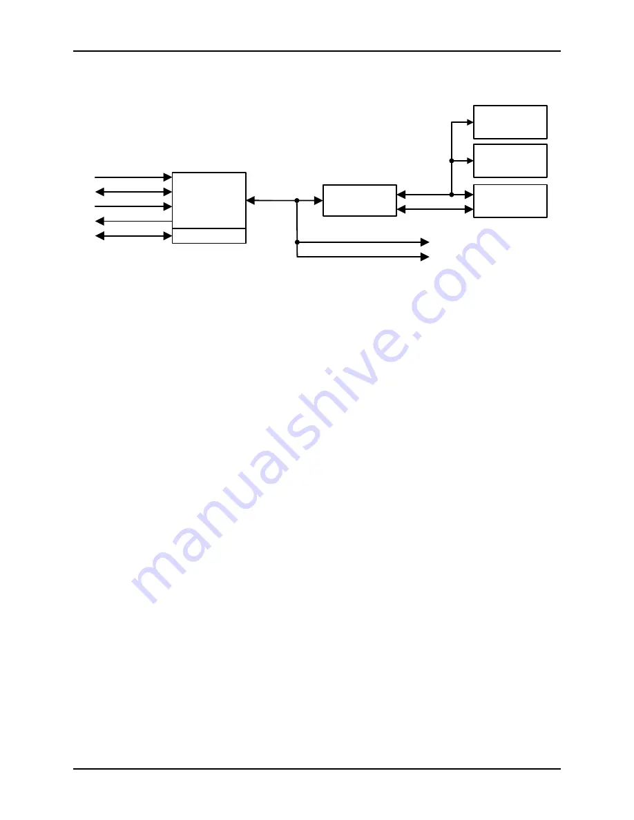
VXI Bridge
ADDRESS
ARBITRATION
VADDR
VDATA
VXI_INT
VCTRL
CONTROL
REGISTERS
SERIAL PROM
EEPROM
TEMPERATURE
MONITOR
CBUS
JTAG
I2C
Data Sequencer Logic
Driver Receiver Logic
TTL/ECL
VXI TRIGGERS
Figure 4-2: T940 VXI Bridge Block Diagram
Terms Used in this Section
VADDR
(VXI Address Bus) The 32 bit backplane address bus
VDATA
(VXI Data Bus) The 32 bit backplane data bus
VCTRL
(VXI Control Bus) The backplane control bus
VXI_INT
(VXI Interrupt Signals) The backplane interrupt signals
VXI TRIGGERS (TTLTRG[0:7], ECLTRG[0,1]) The backplane trigger signals.
CBUS
An internal control bus connecting the arbitration logic to the
Data Sequencers and the Driver/Receiver board’s Control
Logic
JTAG
(Joint Test Action Group, IEEE 1149.1) Serial interface that
allows the serial PROM to be reloaded for in-field system
upgrades
I2C
(Inter-Integrated Circuit) Multi master serial interface that
allows communication to the temperature monitor and
EEPROM
Description
The main purpose of the VXI Bridge is to provide a communication interface
between the VXI backplane and the hardware resources.
Power Converter
The PC converts backplane voltages into digital bias voltages V+ and V- for front
end types DR3E, DR9 and UR14. Its protection circuitry can detect faults in any
of the four on-board power supplies, status of the input fuses, or a high input
current or overcurrent condition. There are three types of power converters, each
of which has seven voltage ranges.
Front end features of the DR3E, DR9 and UR14 have headroom requirements to
the V+ and V- bias voltages. Refer to the specific front end appendix for