User Manual
KDC Series II DC Power Supplies
31
4.2.3
Program Menu
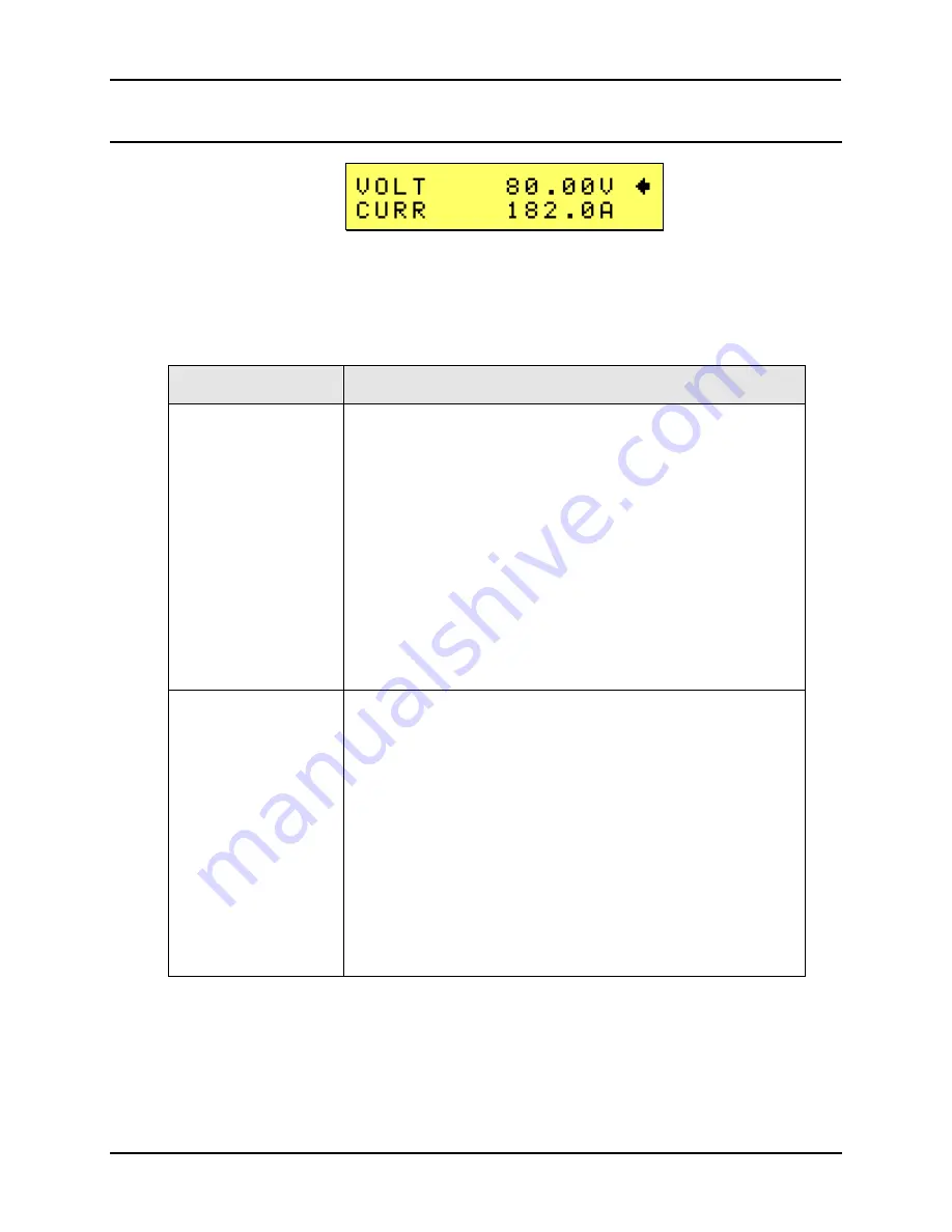
The program menu allows the output of the DC Supply to be programmed. While in the Program
menu, the voltage knobs slews the output voltage up or down and the current knob slews the
current limit value up or down.
There are additional screen at this level but only the first two are visible as shown above. To see
the remaining entries, use the DOWN (
) arrow key to scroll down. These menus can also be
accessed from the CONTROL entry of the main screen. (Level 1)
ENTRY
DESCRIPTION
VOLT
Sets the output voltage. Use the left knob (VOLTAGE) to slew
the voltage value.
SET or SLEW mode data entry:
The voltage can be slewed or set depending on the mode this
screen is in. Press the SET button to enter the set mode while
on the voltage field. The cursor will change to a blinking black
block. Changes made to the voltage will now not take effect
until the ENTER key is pressed. This allows the voltage to be
changed abruptly instead of slewing it. Press the SET key
again to exit the set mode. The blinking cursor will revert back
to the regular underline cursor. Changes made with the voltage
knob will take effect immediately in this mode.
The range is a function of the DC supply model. Refer to the
LIMIT screen to determine the maximum voltage that can be
set. (see paragraph 4.2.12)
CURR
Sets the current limit. Use the right knob (CURRENT) to slew
the current value.
SET or SLEW mode data entry:
The current can be slewed or set depending on the mode this
screen is in. Press the SET button to enter the set mode while
on the current field. The cursor will change to a blinking black
block. Changes made to the current limit will now not take
effect until the ENTER key is pressed. This allows the current
limit to be changed abruptly instead of slewing it. Press the
SET key again to exit the set mode. The blinking cursor will
revert back to the regular underline cursor. Changes made
with the current knob will take effect immediately in this mode.
The range is a function of the DC supply model. Refer to the
LIMIT screen to determine the maximum current that can be
set. (see paragraph 4.2.12)
Summary of Contents for KDC 100-100
Page 2: ......
Page 10: ......
Page 26: ...User Manual 16 KDC Series II DC Power Supplies Figure 3 1 Location of rear panel connectors ...
Page 33: ...User Manual KDC Series II DC Power Supplies 23 Figure 4 3 Front panel layout ...
Page 82: ......
Page 83: ...User Manual KDC Series II DC Power Supplies 73 Figure 6 1 DC Power Supply Block Diagram ...
Page 111: ...User Manual KDC Series II DC Power Supplies 101 Figure 8 2 Replaceable Fuse Locations ...


