background image


Page 

27

 of 

92


4.4 Results 


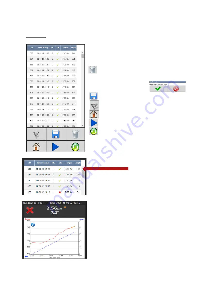
This screen provides a history of rundowns performed. 
Information such as ID Number, Time Stamp, Parameter Set#, 
Accept /Reject status, and Torque and Angle are recorded 
for each rundown. 
 

Deletes individual rundowns by clicking on them 
separately and deleting them in the next screen or 

deleting all rundowns by clicking on the icon at the bottom 
of Results page. A Confirmation 
screen will appear. 


“Save Button”

 saves rundowns as Txt. File 


“Filter Button”


gives filter options in Rundown screen 


“Home Button”

 returns to main display menu 


“Play Button”

 sends you directly to Run Screen 


“Refresh


Button”

 refreshes screen to include latest 

rundowns 


Click on Individual Runs for Rundown 
information 


Example:  Rejected Rundown Information 


Summary of Contents for AcraDyne iPC

Page 1: ...Page 1 of 92 MAN177 rev_08_21_2018 iPC Controller Operator Manual ...

Page 2: ...rom Tool 17 4 Home Page Main Menu 17 4 1 Run Features 18 4 2 PSet 21 4 2 1 Add New PSet 21 4 2 3 TC PM Torque Control Pulse Monitor 22 4 2 4 Advanced Options 23 4 2 5 Manage PSets 23 4 3 Job 24 4 3 1 Add New Job 24 4 3 2 Advanced Options 25 4 4 Results 27 4 4 1 Saving Rundown s 28 4 5 Controller 29 4 5 1 Tool Setup 29 4 5 1 2 Tool Parameters 29 4 5 1 3 Disassembly 30 4 5 2 Tool Service 30 4 5 3 I ...

Page 3: ...update image 46 4 6 5 Identify Controller 46 4 6 6 Record Logs 46 4 6 7 System Status 47 4 6 8 I O Diagnostics 47 4 7 Login 48 4 8 Advanced 48 4 9 1 Login Setup 49 4 9 2 Results Archive 49 4 9 3 Import Settings 50 4 9 4 Export Controller 51 4 9 5 Update Controller 51 4 9 6 Backup Restore 52 4 9 7 Restore Factory Defaults 52 4 9 8 Calibrate Touch Screen 53 4 9 9 Soft Reboot 54 5 Barcode Reader Deta...

Page 4: ...Page 4 of 92 MAN177 rev_08_21_2018 ...

Page 5: ...s and matching outlets will reduce risk of electric shock b Avoid body contact with earthed or grounded surfaces such as pipes radiators ranges and refrigerators There is an increased risk of electric shock if your body is earthed or grounded c Do not expose power tools to rain or wet conditions Water entering a power tool will increase the risk of electric shock d Do not abuse the cord Never use ...

Page 6: ...welry Keep your hair clothing and gloves away from moving parts Loose clothes jewelry or long hair can be caught in moving parts 4 Power tool use and care a Do not force the power tool Use the correct power tool for your application The correct power tool will do the job better and safer at the rate for which it was designed b Do not use the power tool if the switch does not turn on and off Any po...

Page 7: ...or operations different from those intended could result in a hazardous situation 5 Service a Have your power tool serviced by a qualified repair person using only identical replacement parts This will ensure that the safety of the power tool is maintained ...

Page 8: ...B connection used to connect external computer to configure monitor the controller 6 Ethernet Port RJ45 Connection used to connect external computer to configure monitor the controller 7 Serial Port DB 9 Pin M Serial data Output for communication with peripherals such as barcode readers and printers 8 24 Volt I O Connector DB 25 Pin M Input and output of signals for process control 9 Anybus To con...

Page 9: ...low torque Fastening cycle was rejected for not achieving low torque Yellow LED Indicates High Pulse Fastening cycle was rejected for exceeding high pulse Yellow Flashing LED Indicates Low Pulse Fastening cycle was rejected for not achieving low pulse Blue LED Tool is In cycle above threshold Increment Decrement buttons change Pset Toggle button switches secondary display between o Units of measur...

Page 10: ...source Connection to local power should be made in consultation with a qualified electrician Step 4 The Secondary Protective Earth Attachment required must be connected to ground using the 14 AWG conductor a green wire with a yellow stripe Attach using a 10 14AWG ring terminal and 10 star washer see below 1 Secondary Protective Earth Attachment Step 5 Turn controller on by pushing the Power Discon...

Page 11: ...ler touch screen console 2 System Port USB A to B connection Direct connection to controller 3 Ethernet Port Via direct connection or LAN Touchscreen Console Controller functions and programming can be accessed directly through the touch screen 1 Power on controller 2 Run screen will appear 3 Controller is ready for use ...

Page 12: ...s USB Setup Step 1 Power on PC and controller allow enough time for them to become fully operational Step 2 Attach controller to PC using a USB 2 0 A B cable If this is the first time connecting the devices wait for Windows to install the RNDIS driver This should happen automatically Step 3 After the driver is installed go to Control Panel Step 4 Go to Network and Internet ...

Page 13: ...2 Step 5 Go to Network and Sharing Center Step 6 Go to Change adapter settings Step 7 Find the Local Area Connection that is using the USB Ethernet RNDIS Gadget network Right click this network and go to Properties ...

Page 14: ... select Internet Protocol Version 4 and click Properties Step 9 In Properties set the IP address to a static address Type an IP address of 192 168 1 5 Any address on the same subnet as the controller will work Set subnet mask to 255 255 255 0 ...

Page 15: ...age 15 of 92 Step 10 To connect to the controller open a browser such as Chrome or Firefox Enter 192 168 1 4 the default system port IP address You will see the controller software on your computer sceen ...

Page 16: ...ructions see the example earlier in this section To connect to the controller In the Computer Laptop open a browser such as Chrome or Firefox Enter 10 10 30 99 the default Ethernet port IP address You will see on your computer sceen the controller software NOTE Controller does not have a DHCP client it will not automatically configure itself with a useable IP address Consult your Network Administr...

Page 17: ...for the tool connected to the controller It will automatically use the 40 60 and 80 of the rated maximum torque of the tool in a two stage Torque Control Pulse Monitor Strategy TC_PM A prompt will display rated Max Torque and Max RPM of the connected tool for reference These Psets can be modified to meet application requirements 4 Home Page Main Menu ...

Page 18: ...es Time in cycle screen Graph displays curves representing Torque green trace The blue left arrow at the origin of the graph will change the X axis of the rundown curve from Time In Cycle to Time Overall and Angle Below the graph is a historical table that will give information and status of the most recent rundowns including current PSet accepted failed rundown status torque and angle Arrows allo...

Page 19: ...Page 19 of 92 Time Overall Screen Click for curve detail Click on arrow to change curve X axis Choose Time in cycle Time Overall or Angle screen ...

Page 20: ...b display information Run Screen displays real time Job information Large Screen Indicators and Audit information The large screen indicators are helpful in viewing real time results of the rundown from a distance Failed Accepted ...

Page 21: ...etup Manage see Manage PSets On Add New PSet screen below enter appropriate values PSet Number Current PSet to be added Torque Units Unit of measure In Cycle Torque Threshold value at which tool is In Cycle and results from the Rundown will be reported Initial Speed This is the tool output speed in RPM before in cycle torque Speed This is the tool output speed in RPM after in cycle torque Time Lim...

Page 22: ...rget Final desired torque CUT Level Torque Low The lower control limit of the rundown Pulse Bailout If the the number of pulses exceeds this value the tool will stop and the rundown will terminate Pulse High Maximum acceptable pulses Pulse Low Minimum acceptable pulses Additional Pulses After reaching target torque additional pulses to be applied before shutting of the tool Once the desired stage ...

Page 23: ...teristics This value has an inverse relationship with the target torque Output torque Target Torque Ratio Ratio values above 1 0 result in a lower output torque where values below 1 0 result in higher output torques 4 2 5 Manage PSets Save PSets to Browser Allows the PSet information to be saved to the local PC connected to controller PSet information is saved as a txt file and can be opened using...

Page 24: ...b function 4 3 1 Add New Job To add a new Job press on the Home Page Press on Jobs screen above to enter Add New Job screen below Job Number Up to 99 Jobs can be configured Job Name Enter Job Name Job Action Disable Tool Disable tool after job is finished Job complete Icon will appear Tool will not operate until job is reset Reset Job Will reset after Job is finished After appropriate values are e...

Page 25: ...e Enable or Disable Maximum Rejects Number of rejected fasteners allowed Report Missing Fasteners Add an option to each JOB that would allow us to report any missing fasteners When it is set the controller will report an NOK rundown for each fastener that is defined in the JOB but has not been ran These NOK results will be reported whenever a new job is started AND the prior JOB is incomplete Thes...

Page 26: ...nt buttons will change it The two numbers on the PSet Job display will be separated by decimals Pressing the toggle button will change secondary display between o Units of measure o Ethernet IP address o System port IP address o Angle report o Bolt count o Job sequence o Pulse count NOTE Job sequence shows which PSet you are currently on in the job this is not the pset number The first pset in the...

Page 27: ... deleting them in the next screen or deleting all rundowns by clicking on the icon at the bottom of Results page A Confirmation screen will appear Save Button saves rundowns as Txt File Filter Button gives filter options in Rundown screen Home Button returns to main display menu Play Button sends you directly to Run Screen Refresh Button refreshes screen to include latest rundowns Click on Individ...

Page 28: ...editor such as Notepad The format of the Rundown file is tab separated variables and can be viewed using Excel The raw data can now be imported to Excel to build graphs charts etc Contact AIMCO Technical Service for pre made Torque and Angle Templates INDIVIDUAL RUNDOWNS Click on an individual run to view save rundown information SAMPLE OF INDIVIDUAL RUNDOWN INFORMATION ...

Page 29: ...o the controller Tool CAL Value stamped on tool CAL Ratio Calibration factor for matching the torque reading of the tool controller to a torque auditor Maximum Torque Rated maximum torque of the tool This is used when determining the default PSets Rated Speed Rated catalog speed of the tool Optional information only Does not affect the operation of the tool Model Number Optional information only D...

Page 30: ...be disabled Judgment Delay Amount of time after final pulse in disassembly that determines disassembly has been completed 4 5 2 Tool Service Cycles Pre set service intervals that can be tracked by cycle count Pulses Pre set service intervals that can be tracked by pulse count Cycle Limit x1000 Pulse Limit x1000 Service Due Action Four options are available No Action No Action will be taken Log Err...

Page 31: ... enter output Input Configuration screen below 4 5 3 2 Physical IO Monitor Provides monitoring of Physical 24 Volt I O Force on off the individual I O pins for testing of field wiring Each indicator shows the state of the associated pin Green On Red Off Force Enable Disable When Buttons from I O are selected this field selects which Inputs and Outputs can be forced through the Monitor I O screen F...

Page 32: ...ment Shows element being configured Bit Enter Bit Bits of bits the assignment will read Start at Starting bit location Polarity Normally Open or Normally Closed Inputs used in certain Input functions Select desired Input Function s Click on after appropriate selections are made Below is an example of the Anybus Input screen with five Inputs set up Click to change an individual Element or return to...

Page 33: ...Closed Outputs Mode Normal Output signal sent Timed signal sent Time entered in seconds Flash signal sent Time entered in Seconds Select desired Output Function s from list above Click on after appropriate changes are made Below is an example of the Anybus Output screen with five Outputs set up Click on to make changes on an individual Element or return to the Output Configuration screen Will dele...

Page 34: ... IP address of the gateway computer that provides access beyond the local network NOTE Consult your local System Administrator to connect the controller to your Network and assign IP addresses 4 5 4 2 System Port IP Address The IP address of controller s System Port Default is 192 168 1 4 Subnet Mask The Subnet Mask of controller s System Port NOTE It is not recommended to change this setting ...

Page 35: ...tput and Barcode Reader Contact AIMCO Technical Service for detailed information on the following Open Protocol PFCS Modbus RTU Baud Serial ports can be configured for different baud rates available Format See below Output Followed by Null Control Character Pset Change Output Send PSet Change String Format Options Standard Output Format o O P HHHHH LLLLL TTTTT P HHHHH LLLLL AAAAA CR CR NULL O Over...

Page 36: ...acter CR Carriage return control character NULL Null control character if option is selected Standard Output with Carriage Return Line Feed and PSet Format o O P HHHHH LLLLL TTTTT P HHHHH LLLLL AAAAA 1 CR LF NULL O Overall Pass Fail P Pass F Fail P Torque Pass Fail P Pass F Fail HHHHH Torque High Limit Units selected in the PSet X10 LLLLL Torque Low Limit Units selected in the PSet X10 TTTTT Torqu...

Page 37: ...TT T Torque Result Units selected in the PSet AAAA Angle Result Degrees PPPP Pulse Count 0000 J Judgment Overall Pass H Low Torque I High Torque J Low Angle K High Angle G Fault During Fastening CR Carriage return control character NULL Null control character if option is selected Profibus Output Format o CAN 1 O P HHHHH LLLLL TTTTT P HHHHH LLLLL AAAAA NAC CR LF NULL CAN Message Start 1 PSet PSet ...

Page 38: ...rial Format matches UEC 4800 and Gen3 o 1 P BB TTT T AAAA PPPP 0000 J CR NULL Message Start 1 Spindle Number Always 1 P PSet PSet 1 9 for PSets 1 9 A Z for PSets 10 35 BB Job Bolt Count Total number of accepts during the Job TTT T Torque Result Units selected in the PSet AAAA Angle Result Degrees PPPP Pulse Count 0000 J Judgment Overall Pass H Low Torque I High Torque J Low Angle K High Angle G Fa...

Page 39: ...C NULL CAN Message Start 8 A Previous PSet PSet 1 9 for PSets 1 9 A Z for PSets 10 35 NAC CAN 4 B New PSet PSet 1 9 for PSets 1 9 A Z for PSets 10 35 NAC Message End NULL Null control character if option is selected 4 5 4 4 Anybus Node Address Configures the Anybus node address for controller ...

Page 40: ...power up on the job selected When Last job is selected controller will power up on last job selected prior to being Powered Down Last Job Controller will default to last job performed Power Up Job Action Reset Job Job will be reset when controller is Powered Up Wait for job Reset Controller will wait for an External Job reset command upon Power Up and will retain job ormation existing prior to pow...

Page 41: ...ved barcode against The received barcode must be at least as long in length as the Mask The Mask can also contain don t care characters of a decimal point or period in the string These characters are counted in the length however the actual received character in that position doesn t matter Example VIN 123456 Identifier Type Identifies which identifier ID 1 4 received barcode will be stored into I...

Page 42: ...and re enter completed barcode configuration screen Click anywhere in body if additional identifiers are required Press to save barcode configuration See 5 0 Barcode Reader Details for more information To configure Serial Port for Barcode Reader On Home page click controller Communication Interfaces Serial Select Barcode Reader and the correct Baud rate Press to save changes 4 5 8 Set Time Set tim...

Page 43: ...Page 43 of 92 4 5 9 Remote Connections Sets number of remote browser connections to controller 4 5 10 Languages Select from English Chinese Japanese Korean Spanish Portugese Brasil ...

Page 44: ...ven below 4 6 1 Controller Overview Model Number Model Number of the controller Serial Number Serial Number of the controller Type Type of controller IPC Intelligent Pulse Controller Application Current Application software version Firmware Current Firmware software version Servo Current Servo Drive Available Hardware Available hardware on the controller ...

Page 45: ... electronics internal 1 8V Bus voltage CPU Temperature deg C Represents temperature inside controller measured in Celsius Mainboard Temperature Displayed in Celsius Active Faults Any tool controller faults will be shown in this area 4 6 3 Live Tool Features Torque Shows a live view of tool transducer in volts Voltage will be approximately 2 0 volts 0 005 Vdc when tool is at rest and torque is zero...

Page 46: ...oses 4 6 5 Identify Controller Identify Controller will cause lights on controller and tool to flash making the system easy to locate This is especially helpful when programming is being done and multiple controllers are being used near each other 4 6 6 Record Logs Logs information describing usage of controller and tools that have been used with that controller 4 6 6 1 Change Log Log displays cha...

Page 47: ...Page 47 of 92 4 6 7 System Status 4 6 8 I O Diagnostics This screen shows a record of the last changes in state of all the assigned I O that are active Record can be saved to disgnose I O functionality ...

Page 48: ...s screen Three levels of access to the controller are available Operator Run Login screens available Technician Run PSet Job Diagnostics and Login screens available Administrator All screens available 4 8 Advanced The Advanced menu handles complex settings within the controller ...

Page 49: ...ty files with approximately 50 000 rundowns are maintained at a time The user can at any time save the runs to either a USB stick or to the Web as a USV file imported directly into an Excel spreadsheet Using the touchscreen console you can select multiple files to save Using the web option you can select one of these files at a time to save web option is default Select a file and press Select eith...

Page 50: ...O Anybus Modbus and Ethernet IP Spindle This includes any Master Spindle setup i e number of spindles slave IP addresses etc 4 Press to accept the changes 5 Press to proceed 6 Press when the import is complete the controller will restart Import settings that were exported from another controller via a USB flash drive Use this to quickly apply the same settings across several controllers For exampl...

Page 51: ... save PSet and IP address information before upgrading controller Upgrading the AIMCO Gen IV Controller Using the TouchScreen or a System Port browser session navigate to the Advanced menu Click Update Controller and select the latest release See Figure 1 as an example FIGURE 1 AVAILABLE UPDATES Click the green checkmark when ready After the controller restarts the user should see the messages in ...

Page 52: ...dvanced Backup Restore 2 Press Backup to initialize the backup process 3 Press to replace previous backup with current system the backup process will begin 4 Press Restore to initialize the restore process 5 Press to restore all settings and firmware to last backup the restore process will begin 6 The controller will restart when finished 4 9 7 Restore Factory Defaults This allows the user to rese...

Page 53: ... Press to proceed 5 Press when the restore is complete the controller will restart 4 9 8 Calibrate Touch Screen Calibrate Touch Screen Custom and Factory default calibration are available on the controller console 1 From the Home screen navigate to Advanced Calibrate Touch Screen 2 Press to disable the tool 3 Select the settings to be changed by pressing changing it to 4 Press to accept the change...

Page 54: ...ibration is possible Factory Default Calibration This calibrates the touchscreen to the factory defaults 4 9 9 Soft Reboot Restart the controller without turning the power off 1 From the Home screen navigate to Advanced Soft Reboot 2 Press to proceed the controller will restart ...

Page 55: ...pertain to the processing of barcode strings The Barcode Match Table is used to identify the newly received barcode string Which of the four Identifiers ID 1 4 are required to enable the tool Which of the four Identifiers ID 1 4 to reset on a job complete Parameter to disable all barcode reads while a job is in progress If set barcode reads will be disabled after the first fastener is ran until jo...

Page 56: ...e types each with its own job The barcode scan will select the correct job enabling the tool and the scan will be stored into ID 1 Mask ID type Action Reset ID ID 1 ID 2 ID 3 ID 4 VIN 7 ID 1 Select Job 1 No No No No VIN 8 ID 1 Select Job 2 No No No No VIN 9 ID 1 Select Job 3 No No No No The tool enable disable will be controlled by the job settings the correct job will be selected by the barcode s...

Page 57: ...tup We will assign the employee ID to ID 1 the vehicle VIN to ID 2 and the airbag serial number to ID 3 Scanning a new employee ID will reset the other IDs and force a scan of the vehicle VIN and airbag serial number The scan of the vehicle VIN will also select the correct job number Mask Store to Action Reset ID ID 1 ID 2 ID 3 ID 4 EMP ID 1 None No Yes Yes No VIN ID 2 Select Job 1 No No No No SN ...

Page 58: ...parent screen Edit screens Cancel Changes Button Reject the changes made and return to the parent screen Edit screens Add New Button Add a new item Pset Stage Job and other PSet and Job edit screens Edit Button Edit selected Item PSet and Job edit screens Move Up and Down Buttons Move selected item up or down in the sequence order PSet and Job edit screens Copy Button Copy selected Items PSet Job ...

Page 59: ...to enable the tool to run JOB Job Sequence Complete JOB Job Complete JOB XML Count Complete LOR Locked on Reject BRCD Bar Code ID scan required to enable tool SRVC Tool Disabled For Service Tool service or calibration interval has expired INVP Invalid PSet Parameter set number for a non existent Pset has been selected to run Most likely via one of the following methods o Job o MFB o IO INVP PSet o...

Page 60: ...Page 60 of 92 NET XML Disconnected XML Stop from XML NOK XML Max Rejects Exceeded FLT Controller Fault Error has been detected See fault code list for details ...

Page 61: ...ontroller electronics FH21 9vdc out of tolerance 9 Volt bus voltage out of range Faulty power supply or wiring Faulty Controller main board or other Controller electronics Faulty tool cable Faulty tool electronics or wiring FH22 24 volt level low 24 Volt IO power not detected Faulty power supply or wiring Short or other problem with external connections to the 24Volt IO port FH23 Controller temp h...

Page 62: ... FP02 Torque tare value out of range Tool torque signal no load voltage is out of range Faulty tool cable Transducer electronics significantly out of calibration Faulty transducer FP03 Torque Cal signal out of Range Tool does not respond to the full scale voltage CAL single Tool not connected Faulty tool cable Faulty transducer Transducer electronics not calibrated Faulty tool controller electroni...

Page 63: ...urn 9 Input 4 PSet Bit 1 22 24 V Return 10 Input 5 PSet Bit 2 23 24 Vdc 11 Input 6 PSet Bit 3 24 24 Vdc 12 Input 7 Reset Job 25 24 Vdc 13 Input 8 Stop NOTE The Default Assignments in Table above are factory defaults and can be changed See Assignable I O section Volt I O Connections Turn off system before connecting to the LOGIC I O port There may be risk of damaging the controller 24Vdc Supply The...

Page 64: ...stem port to modify the Anybus outputs 1 Power on the controller 2 Insert the USB stick into a USB port 3 Connect to the controller via system port and web browser default address 192 168 1 4 4 Navigate to Advanced Import Settings 5 Select ONLY IO 6 Click OK 7 Click OK in the Confirmation dialog box 8 The controller will restart ...

Page 65: ...ybus outputs a Navigate to Controller IO Anybus Outputs b Click on the first row of element 1 and verify it is set as Running Job Number Bit 0 Bits 8 Start at 0 c Click on element 4 and verify it is set as Torque x100 Bit 0 Bits 16 ...

Page 66: ...ation in the bus The first element on the bus is 0 and goes up the last legal element for the given bus The bits in each element is referenced from 0 LSB to 31 MSB Inputs All input assignments have a Bus Element and Bit configuration to define its location in the system Along with the basic configuration many also have other configuration s that allow its behavior to be modified to suit the applic...

Page 67: ...fines the number of bits the assignment will read for its input This allows the input size to be restricted to a few bits saving space for other assignments The offset variable allows a fixed value to be added to the read value For example to use bits 4 5 of the physical inputs to select parameter sets 1 4 the assignment would look like Select PSet Bus 1 For the physical bus Element 0 For the firs...

Page 68: ...parameter set according to the input value Uses the width parameter limit the width of the input bits read The minimum width is 1 and the maximum is 8 After the input is read the offset parameter will be added to the value do get the actual parameter set number Selecting an invalid parameter set number will disable the tool Select Job Supported Feature Bus Element Bit 0 31 Polarity N O N C Width O...

Page 69: ...aximum value of the input For example a width setting of 16 can have an integer value of 0 65535 so the produced ID would be 00000 to 65535 always five character long Width setting Length of ID string ID value 1 3 1 0 n 4 6 2 00 nn 7 9 3 000 nnn 10 13 4 0000 nnnn 14 16 5 00000 nnnnn 17 19 6 000000 nnnnnn 20 23 7 0000000 nnnnnnn 24 26 8 00000000 nnnnnnnn 27 29 9 000000000 nnnnnnnnn 30 32 10 0000000...

Page 70: ...nput bits read The minimum width is 1 and the maximum is 8 After the input is read the offset parameter will be added to the value do get the actual parameter set number If the parameter set input value does not match the current parameter of the controller the tool will be disabled Clear Results Supported Feature Bus Element Bit 0 31 Polarity N O N C Width Offset The Clear Results assignment will...

Page 71: ...are not removed Verify Job Sequence Supported Feature Bus Element Bit 0 31 Polarity N O N C Width Offset The Verify Job Sequence input will compare the current Job sequence to the input value Uses the width parameter limit the width of the input bits read The minimum width is 1 and the maximum is 8 After the input is read the offset parameter will be added to the value do get the actual Job sequen...

Page 72: ...de Normal Timed Flash Time Width Offset Input Bus Input Element Input Bit iEC iAC iPC iBC iBC Z Ok Nok Torque Ok Torque Nok Low Torque High Torque Angle Ok Angle Nok Low Angle High Angle Fastening Complete In Cycle Fastening Aborted Fastening Stopped Batch Complete Job Complete Error Tool Start Switch Tool Push to Start Switch Tool MFB Tool Enabled Tool Running Service Indicator ToolsNet Connected...

Page 73: ...lete Pulses Pulses High Pulses Low Pulses NOk Pulses Ok Polarity When the polarity is set to N O the output will be high when it is active 24vdc for physical outputs and logic 1 for all network type buses When the polarity is set to N C the output will be low for active 0vdc for physical inputs and logic 0 for all network type buses ...

Page 74: ...on and stay on till the assignment goes to inactive Figure 1 Normal Mode Timed Mode In the Timed mode the output will come on when the assignments state goes active and go off based on the time value or the assignment state going inactive while still observing the polarity setting Figure 2 Timed Mode assignment deactivates before time expires Assignments active state Output state Assignments activ...

Page 75: ...a few bits saving space for other assignments The offset variable allows a fixed value to be added to the value before it is output For example to use bits 4 5 of the physical outputs to indicate the selected parameter set number 1 4 as binary 0 3 the assignment would look like Running PSet Number Bus 1 For the physical bus Element 0 For the first element on the bus Bit 4 For the starting bit loca...

Page 76: ...astening is started the torque exceeds the threshold value or a Job reset Torque Ok Supported Feature Bus Element Bit 0 32 Polarity N O N C Mode Normal Timed Flash Time Width Offset Input Bus Input Element Input Bit The Torque Ok output assignment will go active at the completion of a fastening that has an acceptable torque value It will go inactive when the next fastening is started the torque ex...

Page 77: ...ill go inactive when the next fastening is started the torque exceeds the threshold value or a Job reset Angle Ok Supported Feature Bus Element Bit 0 32 Polarity N O N C Mode Normal Timed Flash Time Width Offset Input Bus Input Element Input Bit The Angle Ok output assignment will go active at the completion of a fastening that has an acceptable angle results It will go inactive when the next fast...

Page 78: ...that has a higha angle results It will go inactive when the next fastening is started the torque exceeds the threshold value or a Job reset Fastening Complete Supported Feature Bus Element Bit 0 32 Polarity N O N C Mode Normal Timed Flash Time Width Offset Input Bus Input Element Input Bit The Fastening Complete output assignment will go active at the completion of a fastening It will go inactive ...

Page 79: ...go inactive when the next fastening is started the torque exceeds the threshold value or a Job reset Batch Complete Supported Feature Bus Element Bit 0 32 Polarity N O N C Mode Normal Timed Flash Time Width Offset Input Bus Input Element Input Bit The Batch Complete output assignment will go active at the completion of a fastening that satisfies the bolt count of a Job sequence It will go inactive...

Page 80: ...O N C Mode Normal Timed Flash Time Width Offset Input Bus Input Element Input Bit The Service Indicator output assignment will be active if the system is in need of service ToolsNet Connected Supported Feature Bus Element Bit 0 32 Polarity N O N C Mode Normal Timed Flash Time Width Offset Input Bus Input Element Input Bit The ToolsNet Connected output assignment will be active if the controller ha...

Page 81: ...et number Running Job Number Supported Feature Bus Element Bit 0 32 Polarity N O N C Mode Normal Timed Flash Time Width Offset Input Bus Input Element Input Bit The Running Job Number output assignment will output the current Job number External Controlled Supported Feature Bus Element Bit 0 32 Polarity N O N C Mode Normal Timed Flash Time Width Offset Input Bus Input Element Input Bit The Externa...

Page 82: ... 32 Polarity N O N C Mode Normal Timed Flash Time Width Offset Input Bus Input Element Input Bit The Torque x100 output assignment will output the final torque value of the most recent rundown The value will be cleared to 0 at the start of a new fastening cycle or a Job reset At the end of the fastening cycle the final torque will be multiplied by 100 truncated to an integer and output Angle Suppo...

Page 83: ...t value of the most recent rundown The value will be cleared to 0 at the start of a new fastening cycle or a Job reset Supported Feature Bus Element Bit 0 32 Polarity N O N C Mode Normal Timed Flash Time Width Offset Input Bus Input Element Input Bit The Pulses Ok output assignment will go active at the completion of a fastening that has an acceptable pulse count It will go inactive when the next ...

Page 84: ...o active at the completion of a fastening that has an pulse count that falls below the low limit It will go inactive when the next fastening is started the torque exceeds the threshold value or a Job reset 10 Controller supported MIDs Supported MID MID Description Revisions Note 1 Communication start 1 2 3 2 Communication start acknowledge 1 2 3 3 Communication stop 4 Command error 5 Command accep...

Page 85: ...tightening result data unsubscribe 64 Old tightening result upload request 65 Old tightening result upload reply 70 Alarm subscribe 71 Alarm 72 Alarm acknowledge 73 Alarm unsubscribe 76 Alarm status 77 Alarm status acknowledge 80 Read time upload request 81 Read time upload reply 82 Set time 90 Multi spindle status subscribe 91 Multi spindle status 92 Multi spindle status acknowledge 91 Multi spin...

Page 86: ...scribe 214 IO device status request 1 2 215 IO device status reply 216 Relay function subscribe See supported relay functions below 217 Relay function 218 Relay function acknowledge 219 Relay function unsubscribe 9999 Keep alive open protocol communication Supported Relay Functions Number Function 1 OK 2 NOK 5 Low Torque 6 High Torque 7 Low angle 8 High angle 9 Cycle complete 10 Alarm 11 Batch NxO...

Page 87: ...Page 87 of 92 11 Dimensions ...

Page 88: ...e SD Card initializing Soultion The rear SD card can be used to easily move the software firmware configuration and rundowns to a new controller in the event of hardware failure This allows the controller to be replaced with a new unit while retaining all the rundown information and configuration settings Remove the rear SD card from the damaged unit and insert it into a functioning unit to perfor...

Page 89: ...ith the development PC In the list RNDIS Kitl can be seen with an exclamation mark implying that driver has not been installed Step 3 Right click on it and select Update Driver Software When prompted choose Browse my computer for driver software to search for device driver software Step 4 Browse for driver software on your computer will come up Select Let me pick from a list of device drivers on m...

Page 90: ...er list Under the list of Network Adapter select Remote NDIS Compatible Device Step 7 The RNDIS Kit device is now installed and ready for use Issue DC Bus High Voltage Warning when using an HT tool Solution Adding a Brake Stop of 0 5 to 1 0 Second stage to the end of the rundown should eliminate this issue ...

Page 91: ... if the customer or any other person other than an authorized representative of AIMCO has made any attempt to service or modify the tool or accessory prior to its return to AIMCO under this Warranty The warranty provision with respect to each such product may be amended by AIMCO from time to time in its sole discretion The liability of AIMCO hereunder shall be limited to replacing or repairing at ...

Page 92: ...OSE OF THIS PROVISION IS TO LIMIT THE POTENTIAL LIABILITY OF AIMCO ARISING OUT OF THIS AGREEMENT AND OR SALE NOTE The AIMCO Warranty confers specific legal rights however some states or jurisdictions may not allow certain exclusions or limitations within this warranty Note All warranty periods addressed herein are determined using a standard shift eight hour work day ...

Reviews: