


Note
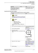
Action
The system parameters that must be
changed (
Upper joint bound
and
Lower joint bound
) are described in
Technical reference manual - System
parameters
.
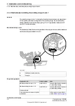
Adjust the software working range limitations
(system parameter configuration) to correspond
to the mechanical limitations.
9
Calibration is detailed in a separate
calibration manual enclosed with the
calibration tools.
Recalibrate the robot!
10
General calibration information is in-
cluded in section
DANGER
Make sure all safety requirements are met when
performing the first test run.
11
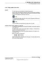
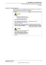
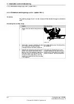
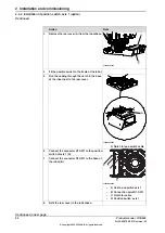
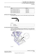
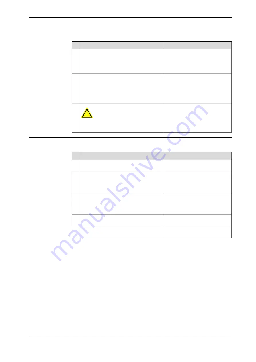
Fitting and adjusting cams and stops
The instruction below details how to fit and adjust the parts of the position switch:
Note
Action
Use a sharp knife and rubber hammer
or similair.
Cut the cam to a suitable length.
1
Shown in the figure
.
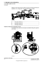
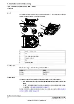
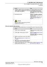
Cut the edge of the cam edge to max 30°!
2
If the angle is larger, this may damage
the position switch!
Cut the part of the cam running in the profile to
90°!
3
Also see the figure
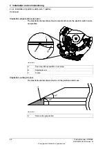
.
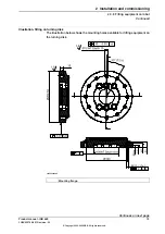
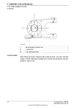
Make sure the ends of the profile are chamfered
to enable the cam to run through the profile.
4
Shown in the figure
Fit the cam with the M5 screw and nut. Tighten
the M5 screw to secure the cam.
5
Continues on next page
Product manual - IRB 660
85
3HAC025755-001 Revision: W
© Copyright 2006-2020 ABB. All rights reserved.
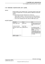
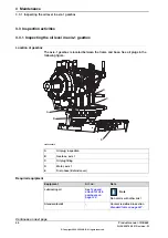
2 Installation and commissioning
2.4.4 Installation of position switch, axis 1 (option)
Continued
Summary of Contents for IRB 660
Page 1: ...ROBOTICS Product manual IRB 660 ...
Page 8: ...This page is intentionally left blank ...
Page 332: ...This page is intentionally left blank ...
Page 352: ...This page is intentionally left blank ...
Page 354: ...This page is intentionally left blank ...
Page 360: ......
Page 361: ......