


Note
Action
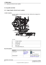
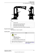
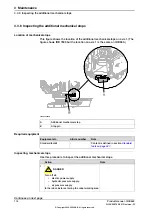
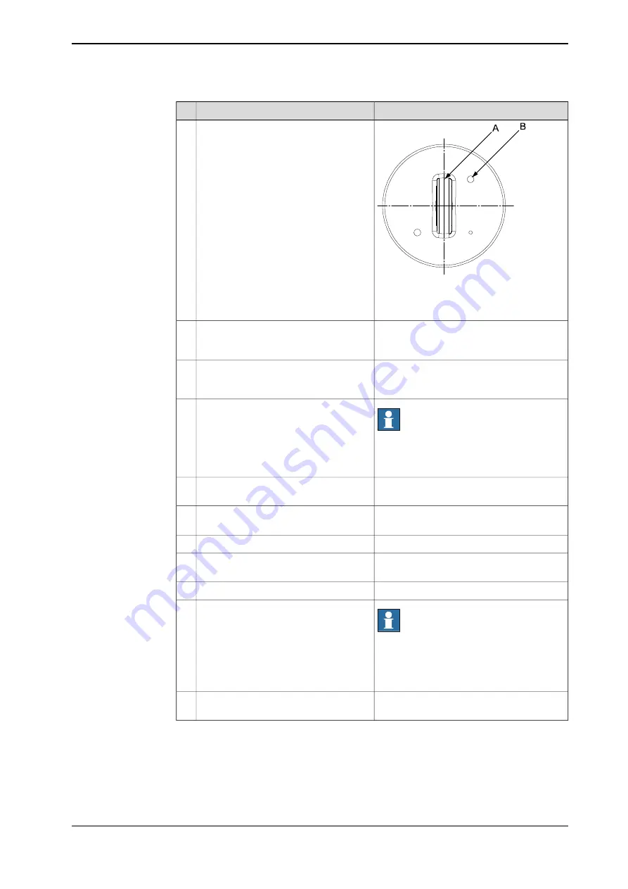
xx0600002687
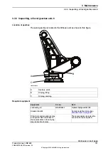
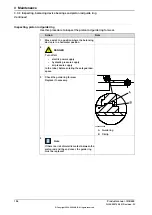
Remove the protection hood from the
M12 hole on top of the balancing device.
5
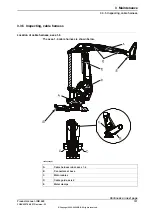
A Attachment (seen from above)
B Protection hood
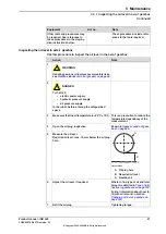
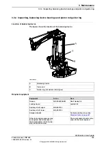
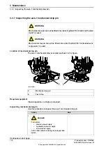
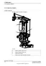
Unload the bearings using a M12x50
screw, in the hole for the protective hood,
at the cylinder top.
6
Shown in previous figure in this procedure.
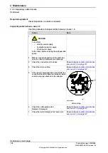
Pull out the cylinder a little, in order to
be able to inspect the
inner rings
without
removing the balancing cylinder.
7
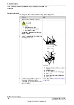
Note
It is quite normal for the bearing races to
have a darker color than the surrounding
material.
Wipe the inner rings clean and check that
there are no pressure marks or other
similar deformations.
8
Shown in previous figure.
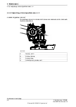
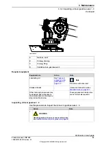
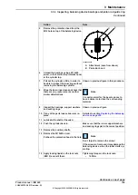
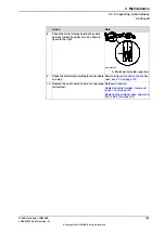
Inspect the
bearings
,
support washers
and
sealing rings
.
9
Detailed in section
.
If any of the parts looks abnormal, re-
place.
10
Lubricate the shafts, if needed.
11
Make sure that the inner support washers
and sealing rings get in the correct position.
Push the cylinder back in.
12
Remove the auxiliary shafts.
13
Note
Don´t forget to remove the screw!
If the screw isn´t removed it may damage the
balancing device, when the robot starts op-
erating.
Remove the M12x50 screw.
Put back the protection hood in the hole.
14
Tightening torque on the lock nuts:
•
120 Nm
Apply
locking liquid
on the lock nuts
(KM10) and refit them.
15
Continues on next page
Product manual - IRB 660
105
3HAC025755-001 Revision: W
© Copyright 2006-2020 ABB. All rights reserved.
3 Maintenance
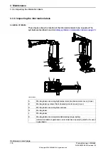
3.3.4 Inspecting, balancing device bearings and piston rod guide ring
Continued
Summary of Contents for IRB 660
Page 1: ...ROBOTICS Product manual IRB 660 ...
Page 8: ...This page is intentionally left blank ...
Page 332: ...This page is intentionally left blank ...
Page 352: ...This page is intentionally left blank ...
Page 354: ...This page is intentionally left blank ...
Page 360: ......
Page 361: ......