


Information
Action
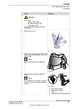
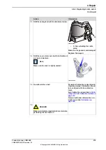
Connect to connector R2.MP6
•
+ : pin 2
•
-: pin 5
In order to release the brake, connect the
24 VDC power supply.
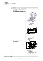
7
xx1000001012
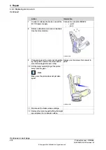
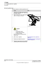
Remove
attachment screws
and
washers
.
Use the bits extension.
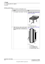
8
Always use the screws for removal in
pairs!
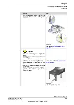
If required, press the motor out of position
by fitting two screws in the motor attach-
ment holes diagonal to each other
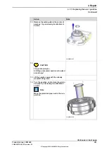
9
xx1000001108
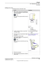
Lift the motor carefully to get the
pinion
away from the gear.
Note
Make sure the
pinion
does not get dam-
aged!
10
Disconnect the brake release voltage.
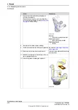
11
Remove the motor by gently lifting it straight
up and place it on a secure surface.
12
Continues on next page
272
Product manual - IRB 660
3HAC025755-001 Revision: W
© Copyright 2006-2020 ABB. All rights reserved.
4 Repair
4.6.3 Replacing motor, axis 6
Continued
Summary of Contents for IRB 660
Page 1: ...ROBOTICS Product manual IRB 660 ...
Page 8: ...This page is intentionally left blank ...
Page 332: ...This page is intentionally left blank ...
Page 352: ...This page is intentionally left blank ...
Page 354: ...This page is intentionally left blank ...
Page 360: ......
Page 361: ......