

Note
Action
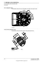
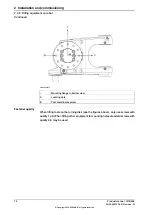
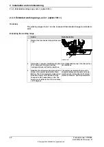
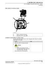
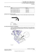
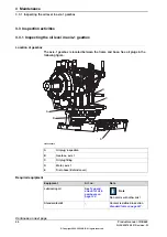
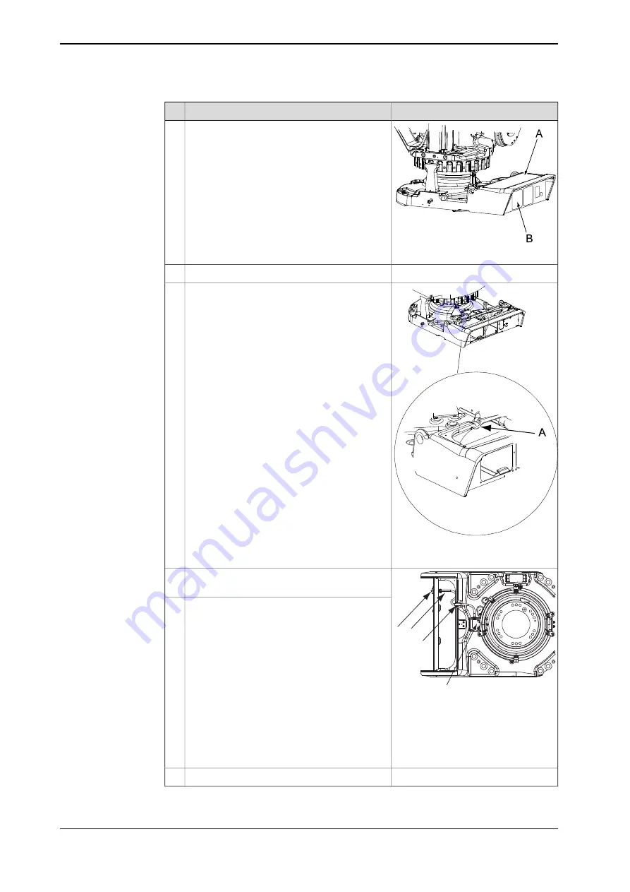
xx0500002306
Remove the rear cover (A) from the robot base.
3
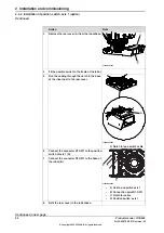
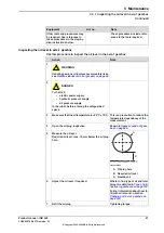
Fit the position switch to the frame of the robot.
4
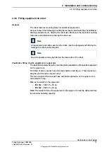
xx0600002625
Run the cabling through the notch in the base
of the robot next to the rear cover.
5
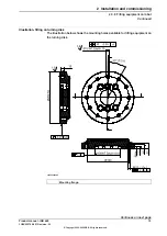
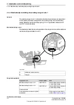
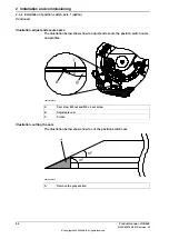
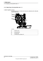
A: Notch for pos.switch cable
A
B
C
D
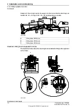
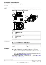
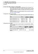
xx0600002626
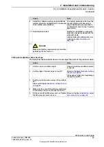
Connect the connector R1.SW1 to the position
switch of axis 1 (D).
6
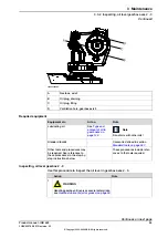
Connect the connector R1.SW1 to the base of
the robot (B).
7
•
A: Cable, pos.switch axis 1
•
B: Connection point R1.SW1
•
C: Notch for cable
•
D: Position switch, axis 1
Refit the rear cover to the robot base.
8
Continues on next page
84
Product manual - IRB 660
3HAC025755-001 Revision: W
© Copyright 2006-2020 ABB. All rights reserved.
2 Installation and commissioning
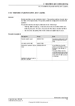
2.4.4 Installation of position switch, axis 1 (option)
Continued
Summary of Contents for IRB 660
Page 1: ...ROBOTICS Product manual IRB 660 ...
Page 8: ...This page is intentionally left blank ...
Page 332: ...This page is intentionally left blank ...
Page 352: ...This page is intentionally left blank ...
Page 354: ...This page is intentionally left blank ...
Page 360: ......
Page 361: ......