


Removing, brake release board
Use this procedure to remove the brake release board.
Note
Action
DANGER
Turn off all:
•
electric power supply to the robot
•
hydraulic pressure supply to the robot
•
air pressure supply to the robot
Before entering the robot working area.
1
ELECTROSTATIC DISCHARGE
(ESD)
The unit is sensitive to ESD. Before handling
the unit read the safety information in section
The unit is sensitive to ESD on page 49
.
2
Shown in the figure
.
Remove the push button guard from the SMB
cover.
3
The guard must be removed to ensure
a correct refitting of the brake release
board.
Shown in the figure
.
Open the SMB cover by unscrewing the attach-
ment screws.
Let the battery stay connected, to avoid the
need of synchronization of the robot!
CAUTION
Clean cover from metal residues before
opening.
Metal residues can cause shortage on the
boards which can result in hazardous failures.
4
Take a picture or make notes of how the robot
cabling is positioned in regard to the brake
release board.
5
Remove the complete brake release board
(including brake release board and bracket)
from the SMB recess, by removing its two at-
tachment screws.
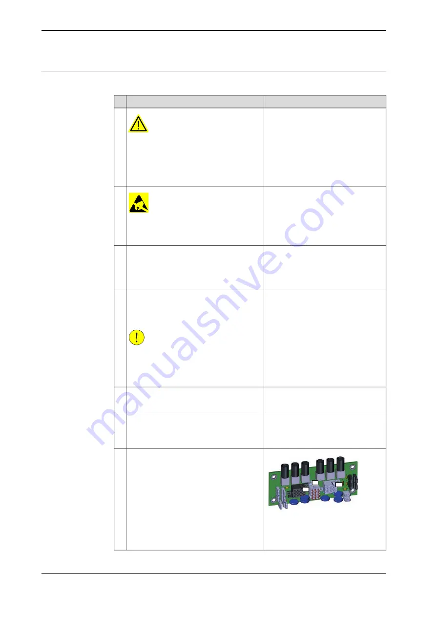
6
X9
X8
X10
xx1700000978
Disconnect the connectors X8, X9 and X10
from the brake release board.
7
Location of the brake release unit is
shown in the figure
.
Continues on next page
248
Product manual - IRB 660
3HAC025755-001 Revision: W
© Copyright 2006-2020 ABB. All rights reserved.
4 Repair
4.5.3 Replacing the brake release board
Continued
Summary of Contents for IRB 660
Page 1: ...ROBOTICS Product manual IRB 660 ...
Page 8: ...This page is intentionally left blank ...
Page 332: ...This page is intentionally left blank ...
Page 352: ...This page is intentionally left blank ...
Page 354: ...This page is intentionally left blank ...
Page 360: ......
Page 361: ......