
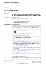
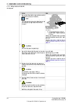
Note
The weight does not include tools and other equipment fitted on the robot.
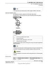
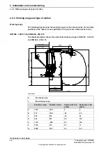
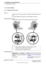
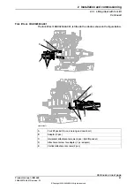
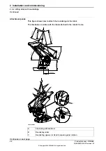
Loads on foundation, robot
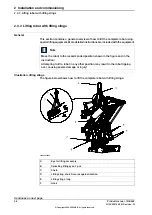
The illustration shows the directions of the robots stress forces.
The directions are valid for all floor mounted, suspended and inverted robots.
xy
xy
z
z
T
F
F
T
xx1100000521
Force in any direction in the XY plane
F
xy
Force in the Z plane
F
z
Bending torque in any direction in the XY plane
T
xy
Bending torque in the Z plane
T
z
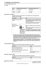
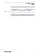
The table shows the various forces and torques working on the robot during different
kinds of operation.
Note
These forces and torques are extreme values that are rarely encountered during
operation. The values also never reach their maximum at the same time!
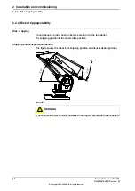
WARNING
The robot installation is restricted to the mounting options given in following load
table(s).
Floor mounted
Max. load (emergency stop)
Endurance load (in operation)
Force
± 11.7 kN
± 8.0 kN
Force xy
Continues on next page
Product manual - IRB 660
43
3HAC025755-001 Revision: W
© Copyright 2006-2020 ABB. All rights reserved.
2 Installation and commissioning
2.2.1 Pre-installation procedure
Continued
Summary of Contents for IRB 660
Page 1: ...ROBOTICS Product manual IRB 660 ...
Page 8: ...This page is intentionally left blank ...
Page 332: ...This page is intentionally left blank ...
Page 352: ...This page is intentionally left blank ...
Page 354: ...This page is intentionally left blank ...
Page 360: ......
Page 361: ......