
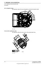
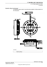

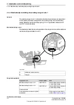
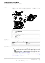
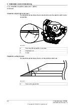

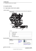

Axis 1
The illustration below shows the position switch for axis 1. The switch is connected
directly to the connector in the base, R1.SW1.
xx0100000158
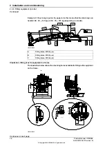
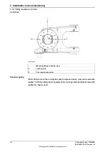
Position switch, axis 1
A
Cam
B
Set screw, cam (cam stop)
C
Protection sheet
D
Rail
E
Rail attachment
F
Specifications
Maximum voltage/current for the position switches:
Value
Parameter
Max. 50 VDC
Voltage
Max. 1 A
Current
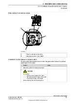
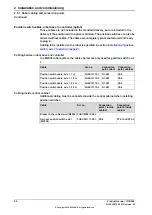
Connections
The position switch is connected to different points on the robot system:
•
XT8, screw terminal in the controller cabinet when position switch cables are
used.
•
R1.SW1 at the robot base. Customer connection set is recommended. Art.no.
is specified in
.
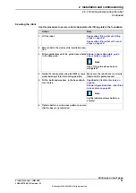
Further information about cables and connection points, see section
and connection points on page 88
Continues on next page
82
Product manual - IRB 660
3HAC025755-001 Revision: W
© Copyright 2006-2020 ABB. All rights reserved.
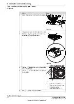
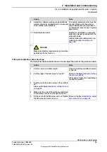
2 Installation and commissioning
2.4.4 Installation of position switch, axis 1 (option)
Continued
Summary of Contents for IRB 660
Page 1: ...ROBOTICS Product manual IRB 660 ...
Page 8: ...This page is intentionally left blank ...
Page 332: ...This page is intentionally left blank ...
Page 352: ...This page is intentionally left blank ...
Page 354: ...This page is intentionally left blank ...
Page 360: ......
Page 361: ......