38 Operation principle and hardware description
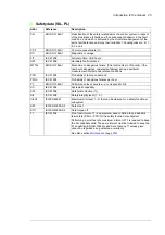
See also
•
•
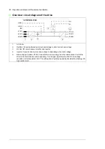
circuit diagrams delivered with drive for the actual wiring.
Terminals for external control voltage (G307)
The option provides terminals for connecting external uninterruptible control voltage to the
control unit and control devices when the drive is not powered.
See also
•
Supplying power for the auxiliary circuits
•
Connecting a 230/115 V AC auxiliary voltage supply (UPS, G307)
on page
•
circuit diagrams delivered with drive for the actual wiring.
Additional terminal block X504 (L504)
The standard terminal blocks of the drive control unit are wired to the additional terminal
block at the factory for customer control wiring. The terminals are spring loaded.
Cables accepted by the terminals:
•
solid wire 0.08 to 4 mm
2
•
stranded wire with ferrule 0.14 to 2.5 mm
2
•
stranded wire without ferrule 0.08 to 2.5 mm
2
(28 to 12 AWG).
Stripping length: 10 mm.
Note
: The optional modules inserted in the slots of the control unit are not wired to the
additional terminal block. The customer must connect the optional module control wires
directly to the modules.
Thermistor relays (oL505, +2L505)
The thermistor relay is used for the overtemperature supervision of motors equipped with
PTC thermistors. When the motor temperature rises to the thermistor wake-up level, the
thermistor resistance increases sharply. The relay detects the change and indicates motor
overtemperature through its auxiliary contacts.
L505 provides a thermistor relay and an auxiliary relay and connection terminals
for one measuring circuit (one PTC thermistor) and for one normally open contact. The
relay can be reset locally or from a remote reset switch wired to the relay.
2L505 provides two thermistor relays and auxiliary relays and connection
terminals for two measuring circuit (one PTC thermistor in each) and for two normally open
contacts. The relays can be reset locally or from a remote reset switch wired to the relay.
The customer connects PTC sensors to the thermistor relay, and the terminals of the
auxiliary relay of the normally open contact, for example, to
•
main breaker control circuit of the drive for opening the breaker in case of motor
overtemperature or
•
appropriate digital input of the drive for tripping the drive and generating a fault
message in case of motor overtemperature or
•
customer control circuit.
Summary of Contents for ACS880-07XT Series
Page 1: ...ABB industrial drives Hardware manual ACS880 07XT drives 400 to 1200 kW ...
Page 4: ......
Page 12: ...12 ...
Page 20: ...20 Safety instructions ...
Page 26: ...26 Introduction to the manual ...
Page 54: ...54 Mechanical installation ...
Page 89: ...Electrical installation 89 PE 11 8 4 9 11 ...
Page 94: ...94 Electrical installation ...
Page 112: ...112 Fault tracing ...
Page 123: ...Maintenance 123 5 6 7 ...
Page 124: ...124 Maintenance 8 10 9 ...
Page 126: ...126 Maintenance 6 5 4 ...
Page 127: ...Maintenance 127 9 8 7 ...
Page 128: ...128 Maintenance 12 11 10 ...
Page 149: ...Dimensions 149 Dimension drawing examples Frame 2 R11 R10 with brake chopper ...
Page 150: ...150 Dimensions Frame 2 R11 R10 without brake chopper ...
Page 153: ...Dimensions 153 Location of input terminals ACS880 07XT 12 pulse ...
Page 154: ...154 Dimensions Location of output terminals ACS880 07XT R10 with du dt ...
Page 155: ...Dimensions 155 Location of output terminals ACS880 07XT R10 without du dt ...
Page 156: ...156 Dimensions Location of output terminals ACS880 07XT R11 with du dt ...
Page 157: ...Dimensions 157 Location of output terminals ACS880 07XT R11 without du dt ...
Page 158: ...158 Dimensions Location of PE terminals ACS880 07XT ...
Page 159: ...Dimensions 159 Location of resistor terminals ACS880 07XT R10 ...
Page 160: ...160 Dimensions Location of resistor terminals ACS880 07XT R11 ...
Page 168: ...www abb com drives www abb com drivespartners 3ABD00043579 Rev C EN 2018 01 01 Contact us ...


