


74 Guidelines for planning the electrical installation
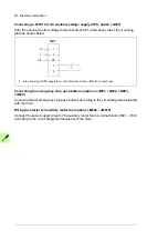
Switching the motor power supply from direct-on-line to drive
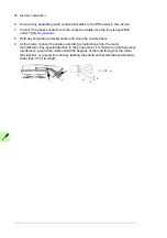
1. Stop the motor with S42.
2. Switch the motor power supply from direct-on-line to the drive with S40.
3. Close the main contactor of the drive with switch S11 (-> turn to position ST for two
seconds and leave to position 1).
4. Start the drive and the motor with the drive control panel (drive in the local control
mode) or the external start signal (drive in the remote control mode).
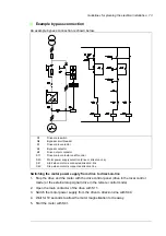
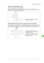
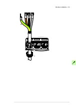
Protecting the contacts of relay outputs
Inductive loads (relays, contactors, motors) cause voltage transients when switched off.
The relay contacts on the drive control unit are protected with varistors (250 V) against
overvoltage peaks. In spite of this, it is highly recommended that inductive loads are
equipped with noise attenuating circuits (varistors, RC filters [AC] or diodes [DC]) in order
to minimize the EMC emission at switch-off. If not suppressed, the disturbances may
connect capacitively or inductively to other conductors in the control cable and form a risk
of malfunction in other parts of the system.
Install the protective component as close to the inductive load as possible. Do not install
protective components at the relay outputs.
1) Relay outputs; 2) Varistor; 3) RC filter; 4) diode
230 V AC
230 V AC
+ 24 V DC
-
1
2
3
4
Summary of Contents for ACS880-07XT Series
Page 1: ...ABB industrial drives Hardware manual ACS880 07XT drives 400 to 1200 kW ...
Page 4: ......
Page 12: ...12 ...
Page 20: ...20 Safety instructions ...
Page 26: ...26 Introduction to the manual ...
Page 54: ...54 Mechanical installation ...
Page 89: ...Electrical installation 89 PE 11 8 4 9 11 ...
Page 94: ...94 Electrical installation ...
Page 112: ...112 Fault tracing ...
Page 123: ...Maintenance 123 5 6 7 ...
Page 124: ...124 Maintenance 8 10 9 ...
Page 126: ...126 Maintenance 6 5 4 ...
Page 127: ...Maintenance 127 9 8 7 ...
Page 128: ...128 Maintenance 12 11 10 ...
Page 149: ...Dimensions 149 Dimension drawing examples Frame 2 R11 R10 with brake chopper ...
Page 150: ...150 Dimensions Frame 2 R11 R10 without brake chopper ...
Page 153: ...Dimensions 153 Location of input terminals ACS880 07XT 12 pulse ...
Page 154: ...154 Dimensions Location of output terminals ACS880 07XT R10 with du dt ...
Page 155: ...Dimensions 155 Location of output terminals ACS880 07XT R10 without du dt ...
Page 156: ...156 Dimensions Location of output terminals ACS880 07XT R11 with du dt ...
Page 157: ...Dimensions 157 Location of output terminals ACS880 07XT R11 without du dt ...
Page 158: ...158 Dimensions Location of PE terminals ACS880 07XT ...
Page 159: ...Dimensions 159 Location of resistor terminals ACS880 07XT R10 ...
Page 160: ...160 Dimensions Location of resistor terminals ACS880 07XT R11 ...
Page 168: ...www abb com drives www abb com drivespartners 3ABD00043579 Rev C EN 2018 01 01 Contact us ...