


Guidelines for planning the electrical installation 69
Implementing thermal overload and short-circuit
protection
Protecting the drive and input power cable in short-circuits
Protect the drive with fuses and the input cable with fuses or a circuit breaker with current
restriction.
Equip the fuses with blown fuse indicators for stopping the drive.
Size the fuses or the circuit breaker according to local regulations for the input cable
protection. Select the fuses for the drive according to the instructions given in chapter
The fuses for the drive protection will restrict drive damage and prevent
damage to adjoining equipment in case of a short-circuit inside the drive.
Circuit breakers
The protective characteristics of circuit breakers depend on the type, construction and
settings of the breakers. There are also limitations pertaining to the short-circuit capacity of
the supply network. Your local ABB representative can help you in selecting the breaker
type when the supply network characteristics are known.
WARNING!
Due to the inherent operating principle and construction of circuit
breakers, independent of the manufacturer, hot ionized gases can escape from
the breaker enclosure in case of a short-circuit. To ensure safe use, pay special
attention to the installation and placement of the breakers. Obey the manufacturer’s
instructions.
Protecting the motor and motor cable in short-circuits
The drive protects the motor cable and motor in a short-circuit situation when the motor
cable is dimensioned according to the nominal current of the drive. No additional
protection devices are needed.
Protecting the drive and the input power and motor cables against
thermal overload
The drive protects itself and the motor cables against thermal overload when the cables
are dimensioned according to the nominal current of the drive. No additional thermal
protection devices are needed.
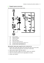
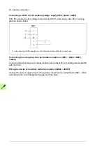
In 6-pulse connection with a common main circuit breaker, the drive protects the input
cables against thermal overload when the cables are dimensioned according to the
nominal current of the drive.
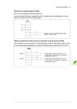
For 12-pulse connection and 6-pulse connection with individual circuit breakers, use gG
fuses with blown fuse indicators for the thermal protection of the input cables. Wire the
indicators to stop the drive in case of a blown fuse.
Summary of Contents for ACS880-07XT Series
Page 1: ...ABB industrial drives Hardware manual ACS880 07XT drives 400 to 1200 kW ...
Page 4: ......
Page 12: ...12 ...
Page 20: ...20 Safety instructions ...
Page 26: ...26 Introduction to the manual ...
Page 54: ...54 Mechanical installation ...
Page 89: ...Electrical installation 89 PE 11 8 4 9 11 ...
Page 94: ...94 Electrical installation ...
Page 112: ...112 Fault tracing ...
Page 123: ...Maintenance 123 5 6 7 ...
Page 124: ...124 Maintenance 8 10 9 ...
Page 126: ...126 Maintenance 6 5 4 ...
Page 127: ...Maintenance 127 9 8 7 ...
Page 128: ...128 Maintenance 12 11 10 ...
Page 149: ...Dimensions 149 Dimension drawing examples Frame 2 R11 R10 with brake chopper ...
Page 150: ...150 Dimensions Frame 2 R11 R10 without brake chopper ...
Page 153: ...Dimensions 153 Location of input terminals ACS880 07XT 12 pulse ...
Page 154: ...154 Dimensions Location of output terminals ACS880 07XT R10 with du dt ...
Page 155: ...Dimensions 155 Location of output terminals ACS880 07XT R10 without du dt ...
Page 156: ...156 Dimensions Location of output terminals ACS880 07XT R11 with du dt ...
Page 157: ...Dimensions 157 Location of output terminals ACS880 07XT R11 without du dt ...
Page 158: ...158 Dimensions Location of PE terminals ACS880 07XT ...
Page 159: ...Dimensions 159 Location of resistor terminals ACS880 07XT R10 ...
Page 160: ...160 Dimensions Location of resistor terminals ACS880 07XT R11 ...
Page 168: ...www abb com drives www abb com drivespartners 3ABD00043579 Rev C EN 2018 01 01 Contact us ...