Control units of the drive 99
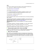
Notes:
The wire size accepted by all screw terminals (for both stranded and solid wire) is
0.5 … 2.5 mm
2
(24…12 AWG). The torque is 0.5 N·m (5 lbf·in).
1)
.
2)
3)
0 = Acceleration/deceleration ramps defined by parameters 23.12/23.13 in use.
1 = Acceleration/deceleration ramps defined by parameters 23.14/23.15 in use.
4)
Constant speed 1 is defined by parameter 22.26.
5)
(page
6)
Total load capacity of these outputs is 4.8 W (200 mA at 24 V) minus the power taken by
DIO1 and DIO2.
7)
Determines whether DICOM is separated from DIOGND (ie. common reference for
digital inputs floats; in practice, selects whether the digital inputs are used in current
sinking or sourcing mode). See also
.
DICOM=DIOGND
ON: DICOM connected to DIOGND. OFF: DICOM and DIOGND
separate.
8)
Current [0(4)…20 mA,
R
in
= 100 ohm] or voltage [0(2)…10 V,
R
in
> 200 kohm] input
selected by switch
AI1
. Change of setting requires reboot of control unit.
9)
Current [0(4)…20 mA,
R
in
= 100 ohm] or voltage [0(2)…10 V,
R
in
> 200 kohm] input
selected by switch
AI2
. Change of setting requires reboot of control unit.
External power supply for the control unit (XPOW)
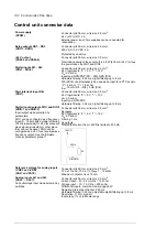
The BCU-x2 is powered from a 24 V DC, 2 A supply through terminal block XPOW. A
second supply can be connected to the same terminal block for redundancy.
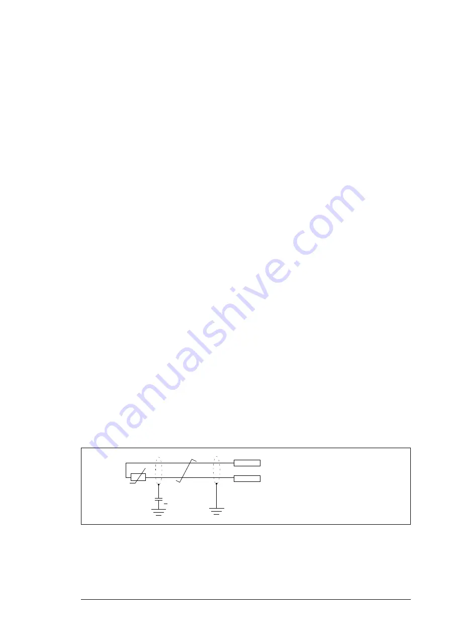
DI6 as a PTC sensor input
A PTC sensor can be connected to this input for motor temperature measurement as
follows. The sensor can alternatively be connected to FEN-xx encoder interface module.
Do not connect both ends of the cable shield directly to ground. If a capacitor cannot be
used at one end, leave that end of the shield unconnected. See the firmware manual for
parameter settings.
T
3.3 nF
> 630 V AC
PTC
DI6
+24VD
Summary of Contents for ACS880-07XT Series
Page 1: ...ABB industrial drives Hardware manual ACS880 07XT drives 400 to 1200 kW ...
Page 4: ......
Page 12: ...12 ...
Page 20: ...20 Safety instructions ...
Page 26: ...26 Introduction to the manual ...
Page 54: ...54 Mechanical installation ...
Page 89: ...Electrical installation 89 PE 11 8 4 9 11 ...
Page 94: ...94 Electrical installation ...
Page 112: ...112 Fault tracing ...
Page 123: ...Maintenance 123 5 6 7 ...
Page 124: ...124 Maintenance 8 10 9 ...
Page 126: ...126 Maintenance 6 5 4 ...
Page 127: ...Maintenance 127 9 8 7 ...
Page 128: ...128 Maintenance 12 11 10 ...
Page 149: ...Dimensions 149 Dimension drawing examples Frame 2 R11 R10 with brake chopper ...
Page 150: ...150 Dimensions Frame 2 R11 R10 without brake chopper ...
Page 153: ...Dimensions 153 Location of input terminals ACS880 07XT 12 pulse ...
Page 154: ...154 Dimensions Location of output terminals ACS880 07XT R10 with du dt ...
Page 155: ...Dimensions 155 Location of output terminals ACS880 07XT R10 without du dt ...
Page 156: ...156 Dimensions Location of output terminals ACS880 07XT R11 with du dt ...
Page 157: ...Dimensions 157 Location of output terminals ACS880 07XT R11 without du dt ...
Page 158: ...158 Dimensions Location of PE terminals ACS880 07XT ...
Page 159: ...Dimensions 159 Location of resistor terminals ACS880 07XT R10 ...
Page 160: ...160 Dimensions Location of resistor terminals ACS880 07XT R11 ...
Page 168: ...www abb com drives www abb com drivespartners 3ABD00043579 Rev C EN 2018 01 01 Contact us ...


