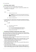
164 Resistor braking
Mechanical installation of external brake resistors
All brake resistors must be installed outside the drive. Obey the resistor manufacturer’s
instructions.
Electrical installation
Checking the insulation of the assembly
Obey the instructions given in section
Brake resistor and resistor cable
.
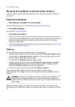
Connection diagram
Connection procedure
•
Connect the resistor cables to the R+ and R- terminals in the same way as the other
power cables. If a shielded three-conductor cable is used, cut the third conductor and
ground the twisted shield of the cable (protective earth conductor of the resistor
assembly) at both ends.
•
Connect the thermal switch of the brake resistor as described in section
system against thermal overload
.
Start-up
Set the following parameters (ACS880 primary control program):
•
Disable the overvoltage control of the drive by parameter
30.30 Overvoltage control
.
•
Set parameter
31.01 External event 1 source
to point to the digital input where the
thermal switch of the brake resistor is wired.
•
Set parameter
31.02 External event 1 type
to
Fault
.
•
Enable the brake chopper by parameter
43.06 Brake chopper enable
. If
Enabled
with thermal model
is selected, set also the brake resistor overload protection
parameters
43.08
and
43.09
according to the application.
•
Check the resistance value of parameter
43.10 Brake resistance
.
With these parameter settings, the drive stops by coasting at brake resistor
overtemperature. For settings of other control programs, see the appropriate firmware
manual.
WARNING!
If the drive is equipped with a brake chopper but the chopper is not
enabled by the parameter setting, the internal thermal protection of the drive
against resistor overheating is not in use. In this case, the brake resistor must be
disconnected.
Note
: Some brake resistors are coated with oil film for protection. At the start-up, the
coating burns off and produces a little bit of smoke. Ensure proper ventilation at the start-
up.
Summary of Contents for ACS880-07XT Series
Page 1: ...ABB industrial drives Hardware manual ACS880 07XT drives 400 to 1200 kW ...
Page 4: ......
Page 12: ...12 ...
Page 20: ...20 Safety instructions ...
Page 26: ...26 Introduction to the manual ...
Page 54: ...54 Mechanical installation ...
Page 89: ...Electrical installation 89 PE 11 8 4 9 11 ...
Page 94: ...94 Electrical installation ...
Page 112: ...112 Fault tracing ...
Page 123: ...Maintenance 123 5 6 7 ...
Page 124: ...124 Maintenance 8 10 9 ...
Page 126: ...126 Maintenance 6 5 4 ...
Page 127: ...Maintenance 127 9 8 7 ...
Page 128: ...128 Maintenance 12 11 10 ...
Page 149: ...Dimensions 149 Dimension drawing examples Frame 2 R11 R10 with brake chopper ...
Page 150: ...150 Dimensions Frame 2 R11 R10 without brake chopper ...
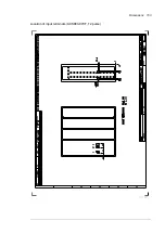
Page 153: ...Dimensions 153 Location of input terminals ACS880 07XT 12 pulse ...
Page 154: ...154 Dimensions Location of output terminals ACS880 07XT R10 with du dt ...
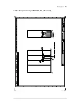
Page 155: ...Dimensions 155 Location of output terminals ACS880 07XT R10 without du dt ...
Page 156: ...156 Dimensions Location of output terminals ACS880 07XT R11 with du dt ...
Page 157: ...Dimensions 157 Location of output terminals ACS880 07XT R11 without du dt ...
Page 158: ...158 Dimensions Location of PE terminals ACS880 07XT ...
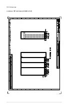
Page 159: ...Dimensions 159 Location of resistor terminals ACS880 07XT R10 ...
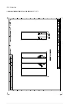
Page 160: ...160 Dimensions Location of resistor terminals ACS880 07XT R11 ...
Page 168: ...www abb com drives www abb com drivespartners 3ABD00043579 Rev C EN 2018 01 01 Contact us ...


