


Resistor braking 163
Maximum cable length
The maximum length of the resistor cable(s) is 10 m (33 ft).
EMC compliance of the complete installation
Note
: ABB has not verified that the EMC requirements are fulfilled with external user-
defined brake resistors and cabling. The EMC compliance of the complete installation
must be considered by the customer.
Placing the brake resistors
Install the resistors outside the drive module in a place where they will cool.
Arrange the cooling of the resistor in a way that:
•
no danger of overheating is caused to the resistor or nearby materials
•
the temperature of the room the resistor is located in does not exceed the allowed
maximum.
Supply the resistor with cooling air/water according to the resistor manufacturer’s
instructions.
WARNING!
The materials near the brake resistor must be non-flammable. The
surface temperature of the resistor is high. Air flowing from the resistor is of
hundreds of degrees Celsius. If the exhaust vents are connected to a ventilation
system, ensure that the material withstands high temperatures. Protect the resistor against
contact.
Protecting the system against thermal overload
The brake chopper protects itself and the resistor cables against thermal overload when
the cables are dimensioned according to the nominal current of the drive. The drive control
program includes a resistor and resistor cable thermal protection function which can be
tuned by the user. See the firmware manual.
A main contactor is not required for protecting against resistor overheating when the
resistor is dimensioned according to the instructions and the internal brake chopper is in
use. The drive will disable power flow through the input bridge if the chopper remains
conductive in a fault situation but the charging resistor may fail.
Note
: If an external brake chopper (outside the drive module) is used, a main contactor is
always required.
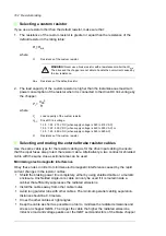
A thermal switch (standard in ABB resistors) is required for safety reasons. The thermal
switch cable must be shielded and may not be longer than the resistor cable. Wire the
switch to a digital input on the drive control unit as shown in the figure below.
Protecting the resistor cable against short-circuits
The input fuses will also protect the resistor cable when it is identical with the input cable.
+24VD
x
DIx
x
Summary of Contents for ACS880-07XT Series
Page 1: ...ABB industrial drives Hardware manual ACS880 07XT drives 400 to 1200 kW ...
Page 4: ......
Page 12: ...12 ...
Page 20: ...20 Safety instructions ...
Page 26: ...26 Introduction to the manual ...
Page 54: ...54 Mechanical installation ...
Page 89: ...Electrical installation 89 PE 11 8 4 9 11 ...
Page 94: ...94 Electrical installation ...
Page 112: ...112 Fault tracing ...
Page 123: ...Maintenance 123 5 6 7 ...
Page 124: ...124 Maintenance 8 10 9 ...
Page 126: ...126 Maintenance 6 5 4 ...
Page 127: ...Maintenance 127 9 8 7 ...
Page 128: ...128 Maintenance 12 11 10 ...
Page 149: ...Dimensions 149 Dimension drawing examples Frame 2 R11 R10 with brake chopper ...
Page 150: ...150 Dimensions Frame 2 R11 R10 without brake chopper ...
Page 153: ...Dimensions 153 Location of input terminals ACS880 07XT 12 pulse ...
Page 154: ...154 Dimensions Location of output terminals ACS880 07XT R10 with du dt ...
Page 155: ...Dimensions 155 Location of output terminals ACS880 07XT R10 without du dt ...
Page 156: ...156 Dimensions Location of output terminals ACS880 07XT R11 with du dt ...
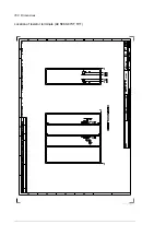
Page 157: ...Dimensions 157 Location of output terminals ACS880 07XT R11 without du dt ...
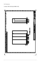
Page 158: ...158 Dimensions Location of PE terminals ACS880 07XT ...
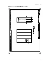
Page 159: ...Dimensions 159 Location of resistor terminals ACS880 07XT R10 ...
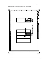
Page 160: ...160 Dimensions Location of resistor terminals ACS880 07XT R11 ...
Page 168: ...www abb com drives www abb com drivespartners 3ABD00043579 Rev C EN 2018 01 01 Contact us ...