


Safety instructions 19
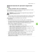
Additional instructions for permanent magnet motor
drives
Safety in installation, start-up and maintenance
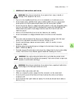
These are additional warnings concerning permanent magnet motor drives. The other
safety instructions in this chapter are also valid.
WARNING!
Obey these
instructions. If you ignore them, injury or death and
equipment malfunction can occur.
•
Do not do work on the drive when the permanent magnet motor is rotating. A rotating
permanent magnet motor energizes the drive including its input power terminals.
Before installation, start-up and maintenance work on the drive:
•
Stop the motor.
•
Disconnect the motor from the drive with a safety switch or by other means.
•
If you cannot disconnect the motor, make sure that the motor cannot rotate during
work. Make sure that no other system, like hydraulic crawling drives, can rotate the
motor directly or through any mechanical connection like felt, nip, rope, etc.
•
Measure that the installation is de-energized.
•
Use a multimeter with an impedance of at least 1 Mohm.
•
Make sure that the voltage between the drive output terminals (T1/U2, T2/V2,
T3/W2) and the grounding (PE) busbar is close to 0 V.
•
Make sure that the voltage between the drive input power terminals (L1/U1, L2/V1,
L3/W1) and the grounding (PE) busbar is close to 0 V.
•
Make sure that the voltage between the drive module UDC+ and UDC- terminals
and the grounding (PE) busbar is close to 0 V.
•
Install temporary grounding to the drive output terminals (T1/U2, T2/V2, T3/W2).
Connect the output terminals together as well as to the PE.
•
Make sure that the operator cannot run the motor over the rated speed. Motor
overspeed causes overvoltage can damage or explode the capacitors in the
intermediate circuit of the drive.
Summary of Contents for ACS880-07XT Series
Page 1: ...ABB industrial drives Hardware manual ACS880 07XT drives 400 to 1200 kW ...
Page 4: ......
Page 12: ...12 ...
Page 20: ...20 Safety instructions ...
Page 26: ...26 Introduction to the manual ...
Page 54: ...54 Mechanical installation ...
Page 89: ...Electrical installation 89 PE 11 8 4 9 11 ...
Page 94: ...94 Electrical installation ...
Page 112: ...112 Fault tracing ...
Page 123: ...Maintenance 123 5 6 7 ...
Page 124: ...124 Maintenance 8 10 9 ...
Page 126: ...126 Maintenance 6 5 4 ...
Page 127: ...Maintenance 127 9 8 7 ...
Page 128: ...128 Maintenance 12 11 10 ...
Page 149: ...Dimensions 149 Dimension drawing examples Frame 2 R11 R10 with brake chopper ...
Page 150: ...150 Dimensions Frame 2 R11 R10 without brake chopper ...
Page 153: ...Dimensions 153 Location of input terminals ACS880 07XT 12 pulse ...
Page 154: ...154 Dimensions Location of output terminals ACS880 07XT R10 with du dt ...
Page 155: ...Dimensions 155 Location of output terminals ACS880 07XT R10 without du dt ...
Page 156: ...156 Dimensions Location of output terminals ACS880 07XT R11 with du dt ...
Page 157: ...Dimensions 157 Location of output terminals ACS880 07XT R11 without du dt ...
Page 158: ...158 Dimensions Location of PE terminals ACS880 07XT ...
Page 159: ...Dimensions 159 Location of resistor terminals ACS880 07XT R10 ...
Page 160: ...160 Dimensions Location of resistor terminals ACS880 07XT R11 ...
Page 168: ...www abb com drives www abb com drivespartners 3ABD00043579 Rev C EN 2018 01 01 Contact us ...