


Maintenance 121
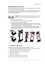
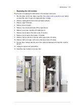
Replacing the drive module
This replacing procedure requires: two persons, installation ramp, a set of screw drivers
and a torque wrench with an extension bar.
The drawings show frame R11. The details in frame R10 are slightly different. There are
two modules in ACS880-07XT. Replacing of each module is introduced respectively
because of different installation.
WARNING!
Obey the instructions in chapter
ignore them, injury or death, or damage to the equipment can occur.
•
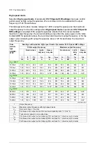
Handle the drive module carefully:
•
Use safety shoes with a metal toe cap to avoid foot injury.
•
Lift the drive module only by the lifting lugs.
•
Make sure that the module does not topple over when you move it on the floor:
Open the support legs by pressing each leg a little down (1, 2) and turning it aside.
Whenever possible secure the module also with chains.
•
Do not tilt the drive module (A).
It is
heavy
and its
center of gravity is high.
The
module overturns from a sideways tilt of 5 degrees. Do not leave the module
unattended on a sloping floor.
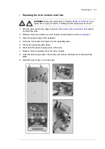
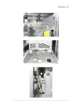
Replacing the right module
The Process of replacing the right module in the cabinet is as below.
1. Stop the drive and do the steps in section
Precautions before electrical work
before
you start the work. Prepare to unplug right drive module.
2. Remove metal grid (Grid was removed below picture).
3. Remove upper bracket.
4. Remove the Shield of fan.
5. Remove three screws at the top of the module.
6. Remove two screws at the bottom of the module.
1
2
3
A
Summary of Contents for ACS880-07XT Series
Page 1: ...ABB industrial drives Hardware manual ACS880 07XT drives 400 to 1200 kW ...
Page 4: ......
Page 12: ...12 ...
Page 20: ...20 Safety instructions ...
Page 26: ...26 Introduction to the manual ...
Page 54: ...54 Mechanical installation ...
Page 89: ...Electrical installation 89 PE 11 8 4 9 11 ...
Page 94: ...94 Electrical installation ...
Page 112: ...112 Fault tracing ...
Page 123: ...Maintenance 123 5 6 7 ...
Page 124: ...124 Maintenance 8 10 9 ...
Page 126: ...126 Maintenance 6 5 4 ...
Page 127: ...Maintenance 127 9 8 7 ...
Page 128: ...128 Maintenance 12 11 10 ...
Page 149: ...Dimensions 149 Dimension drawing examples Frame 2 R11 R10 with brake chopper ...
Page 150: ...150 Dimensions Frame 2 R11 R10 without brake chopper ...
Page 153: ...Dimensions 153 Location of input terminals ACS880 07XT 12 pulse ...
Page 154: ...154 Dimensions Location of output terminals ACS880 07XT R10 with du dt ...
Page 155: ...Dimensions 155 Location of output terminals ACS880 07XT R10 without du dt ...
Page 156: ...156 Dimensions Location of output terminals ACS880 07XT R11 with du dt ...
Page 157: ...Dimensions 157 Location of output terminals ACS880 07XT R11 without du dt ...
Page 158: ...158 Dimensions Location of PE terminals ACS880 07XT ...
Page 159: ...Dimensions 159 Location of resistor terminals ACS880 07XT R10 ...
Page 160: ...160 Dimensions Location of resistor terminals ACS880 07XT R11 ...
Page 168: ...www abb com drives www abb com drivespartners 3ABD00043579 Rev C EN 2018 01 01 Contact us ...