


66 Guidelines for planning the electrical installation
Motor cable shield
If the motor cable shield is used as the sole protective earth conductor of the motor, make
sure that the conductivity of the shield is sufficient. See subsection
above, or
IEC 61439-1. To effectively suppress radiated and conducted radio-frequency emissions,
the cable shield conductivity must be at least 1/10 of the phase conductor conductivity.
The requirements are easily met with a copper or aluminum shield. The minimum
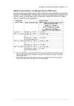
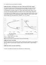
requirement of the motor cable shield of the drive is shown below. It consists of a
concentric layer of copper wires with an open helix of copper tape or copper wire. The
better and tighter the shield, the lower the emission level and bearing currents.
Armored cable / shielded power cable
Six conductor (3 phases and 3 ground) type MC continuous corrugated aluminum armor
cable with symmetrical grounds is available from the following suppliers (trade names in
parentheses):
•
Anixter Wire & Cable (Philsheath)
•
BICC General Corp (Philsheath)
•
Rockbestos Co. (Gardex)
•
Oaknite (CLX).
Shielded power cables are available from Belden, LAPPKABEL (ÖLFLEX) and Pirelli.
Planning the braking system
Selecting the control cables
Shielding
All control cables must be shielded.
Use a double-shielded twisted pair cable for analog signals. We recommend this type of
cable for the pulse encoder signals also. Employ one individually shielded pair for each
signal. Do not use common return for different analog signals.
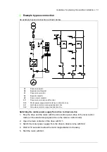
1
Insulation jacket
2
Copper wire screen
3
Helix of copper tape or copper wire
4
Inner insulation
5
Cable core
1
2
3
4
5
Summary of Contents for ACS880-07XT Series
Page 1: ...ABB industrial drives Hardware manual ACS880 07XT drives 400 to 1200 kW ...
Page 4: ......
Page 12: ...12 ...
Page 20: ...20 Safety instructions ...
Page 26: ...26 Introduction to the manual ...
Page 54: ...54 Mechanical installation ...
Page 89: ...Electrical installation 89 PE 11 8 4 9 11 ...
Page 94: ...94 Electrical installation ...
Page 112: ...112 Fault tracing ...
Page 123: ...Maintenance 123 5 6 7 ...
Page 124: ...124 Maintenance 8 10 9 ...
Page 126: ...126 Maintenance 6 5 4 ...
Page 127: ...Maintenance 127 9 8 7 ...
Page 128: ...128 Maintenance 12 11 10 ...
Page 149: ...Dimensions 149 Dimension drawing examples Frame 2 R11 R10 with brake chopper ...
Page 150: ...150 Dimensions Frame 2 R11 R10 without brake chopper ...
Page 153: ...Dimensions 153 Location of input terminals ACS880 07XT 12 pulse ...
Page 154: ...154 Dimensions Location of output terminals ACS880 07XT R10 with du dt ...
Page 155: ...Dimensions 155 Location of output terminals ACS880 07XT R10 without du dt ...
Page 156: ...156 Dimensions Location of output terminals ACS880 07XT R11 with du dt ...
Page 157: ...Dimensions 157 Location of output terminals ACS880 07XT R11 without du dt ...
Page 158: ...158 Dimensions Location of PE terminals ACS880 07XT ...
Page 159: ...Dimensions 159 Location of resistor terminals ACS880 07XT R10 ...
Page 160: ...160 Dimensions Location of resistor terminals ACS880 07XT R11 ...
Page 168: ...www abb com drives www abb com drivespartners 3ABD00043579 Rev C EN 2018 01 01 Contact us ...