


Introduction to the manual 25
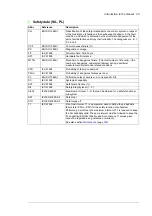
Safety data (SIL, PL)
Abbr.
Reference
Description
Cat.
EN ISO 13849-1
Classification of the safety-related parts of a control system in respect
of their resistance to faults and their subsequent behavior in the fault
condition, and which is achieved by the structural arrangement of the
parts, fault detection and/or by their reliability. The categories are: B, 1,
2, 3 and 4.
CCF
EN ISO 13849-1
Common cause failure (%)
DC
EN ISO 13849-1
Diagnostic coverage
FIT
IEC 61508
Failure in time: 1E-9 hours
HFT
IEC 61508
Hardware fault tolerance
MTTF
d
EN ISO 13849-1
Mean time to dangerous failure: (The total number of life units) / (the
number of dangerous, undetected failures) during a particular
measurement interval under stated conditions
PFD
IEC 61508
Probability of failure on demand
PFH
D
IEC 61508
Probability of dangerous failures per hour
PL
EN ISO 13849-1
Performance level. Levels a…e correspond to SIL
SC
IEC 61508
Systematic capability
SFF
IEC 61508
Safe failure fraction (%)
SIL
IEC 61508
Safety integrity level (1…3)
SILCL
IEC/EN 62061
Maximum SIL (level 1…3) that can be claimed for a safety function or
subsystem
SS1
IEC/EN 61800-5-2
Safe stop 1
STO
IEC/EN 61800-5-2
Safe torque off
T1
IEC 61508
Proof test interval. T1 is a parameter used to define the probabilistic
failure rate (PFH or PFD) for the safety function or subsystem.
Performing a proof test at a maximum interval of T1 is required to keep
the SIL capability valid. The same interval must be followed to keep the
PL capability (EN ISO 13849) valid. Note that any T1 values given
cannot be regarded as a guarantee or warranty.
See also section
Summary of Contents for ACS880-07XT Series
Page 1: ...ABB industrial drives Hardware manual ACS880 07XT drives 400 to 1200 kW ...
Page 4: ......
Page 12: ...12 ...
Page 20: ...20 Safety instructions ...
Page 26: ...26 Introduction to the manual ...
Page 54: ...54 Mechanical installation ...
Page 89: ...Electrical installation 89 PE 11 8 4 9 11 ...
Page 94: ...94 Electrical installation ...
Page 112: ...112 Fault tracing ...
Page 123: ...Maintenance 123 5 6 7 ...
Page 124: ...124 Maintenance 8 10 9 ...
Page 126: ...126 Maintenance 6 5 4 ...
Page 127: ...Maintenance 127 9 8 7 ...
Page 128: ...128 Maintenance 12 11 10 ...
Page 149: ...Dimensions 149 Dimension drawing examples Frame 2 R11 R10 with brake chopper ...
Page 150: ...150 Dimensions Frame 2 R11 R10 without brake chopper ...
Page 153: ...Dimensions 153 Location of input terminals ACS880 07XT 12 pulse ...
Page 154: ...154 Dimensions Location of output terminals ACS880 07XT R10 with du dt ...
Page 155: ...Dimensions 155 Location of output terminals ACS880 07XT R10 without du dt ...
Page 156: ...156 Dimensions Location of output terminals ACS880 07XT R11 with du dt ...
Page 157: ...Dimensions 157 Location of output terminals ACS880 07XT R11 without du dt ...
Page 158: ...158 Dimensions Location of PE terminals ACS880 07XT ...
Page 159: ...Dimensions 159 Location of resistor terminals ACS880 07XT R10 ...
Page 160: ...160 Dimensions Location of resistor terminals ACS880 07XT R11 ...
Page 168: ...www abb com drives www abb com drivespartners 3ABD00043579 Rev C EN 2018 01 01 Contact us ...