


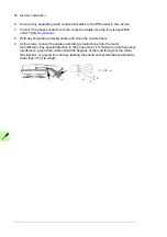

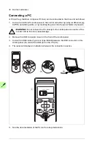


78 Electrical installation
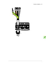
Note 1
: Keep the shields continuous as close to the connection terminals as possible.
Secure the cables mechanically at the lead-through strain relief.
Note 2:
If the outer surface of the shield is non-conductive:
•
Cut the shield at the midpoint of the bare part. Be careful not to cut the conductors or
the grounding wire (if present).
•
Turn the shield inside out to expose its conductive surface.
•
Cover the turned shield and the stripped cable with copper foil to keep the shielding
continuous.
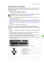
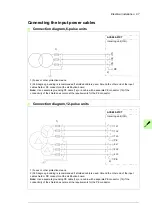
Note for top entry of cables:
When each cable has its own rubber grommet, sufficient IP
and EMC protection can be achieved. However, if very many control cables come to one
cabinet, plan the installation beforehand as follows:
1. Make a list of the cables coming to the cabinet.
2. Sort the cables going to the left into one group and the cables going to the right into
another group to avoid unnecessary crossing of cables inside the cabinet.
3. Sort the cables in each group according to size.
4. Group the cables for each grommet as follows ensuring that each cable has a proper
contact to the cushions on both sides.
Cable diameter in mm
Max. number of cables per grommet
< 13
4
< 17
3
< 25
2
> 25
1
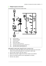
A
Stripped cable
B
Conductive surface of the shield exposed
C
Stripped part covered with copper foil
1
Cable shield
2
Copper foil
3
Shielded twisted pair
4
Grounding wire
1
A
B
C
2
2
3
4
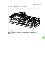
Summary of Contents for ACS880-07XT Series
Page 1: ...ABB industrial drives Hardware manual ACS880 07XT drives 400 to 1200 kW ...
Page 4: ......
Page 12: ...12 ...
Page 20: ...20 Safety instructions ...
Page 26: ...26 Introduction to the manual ...
Page 54: ...54 Mechanical installation ...
Page 89: ...Electrical installation 89 PE 11 8 4 9 11 ...
Page 94: ...94 Electrical installation ...
Page 112: ...112 Fault tracing ...
Page 123: ...Maintenance 123 5 6 7 ...
Page 124: ...124 Maintenance 8 10 9 ...
Page 126: ...126 Maintenance 6 5 4 ...
Page 127: ...Maintenance 127 9 8 7 ...
Page 128: ...128 Maintenance 12 11 10 ...
Page 149: ...Dimensions 149 Dimension drawing examples Frame 2 R11 R10 with brake chopper ...
Page 150: ...150 Dimensions Frame 2 R11 R10 without brake chopper ...
Page 153: ...Dimensions 153 Location of input terminals ACS880 07XT 12 pulse ...
Page 154: ...154 Dimensions Location of output terminals ACS880 07XT R10 with du dt ...
Page 155: ...Dimensions 155 Location of output terminals ACS880 07XT R10 without du dt ...
Page 156: ...156 Dimensions Location of output terminals ACS880 07XT R11 with du dt ...
Page 157: ...Dimensions 157 Location of output terminals ACS880 07XT R11 without du dt ...
Page 158: ...158 Dimensions Location of PE terminals ACS880 07XT ...
Page 159: ...Dimensions 159 Location of resistor terminals ACS880 07XT R10 ...
Page 160: ...160 Dimensions Location of resistor terminals ACS880 07XT R11 ...
Page 168: ...www abb com drives www abb com drivespartners 3ABD00043579 Rev C EN 2018 01 01 Contact us ...