134 Technical data
Ambient temperature derating
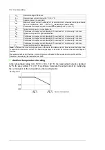
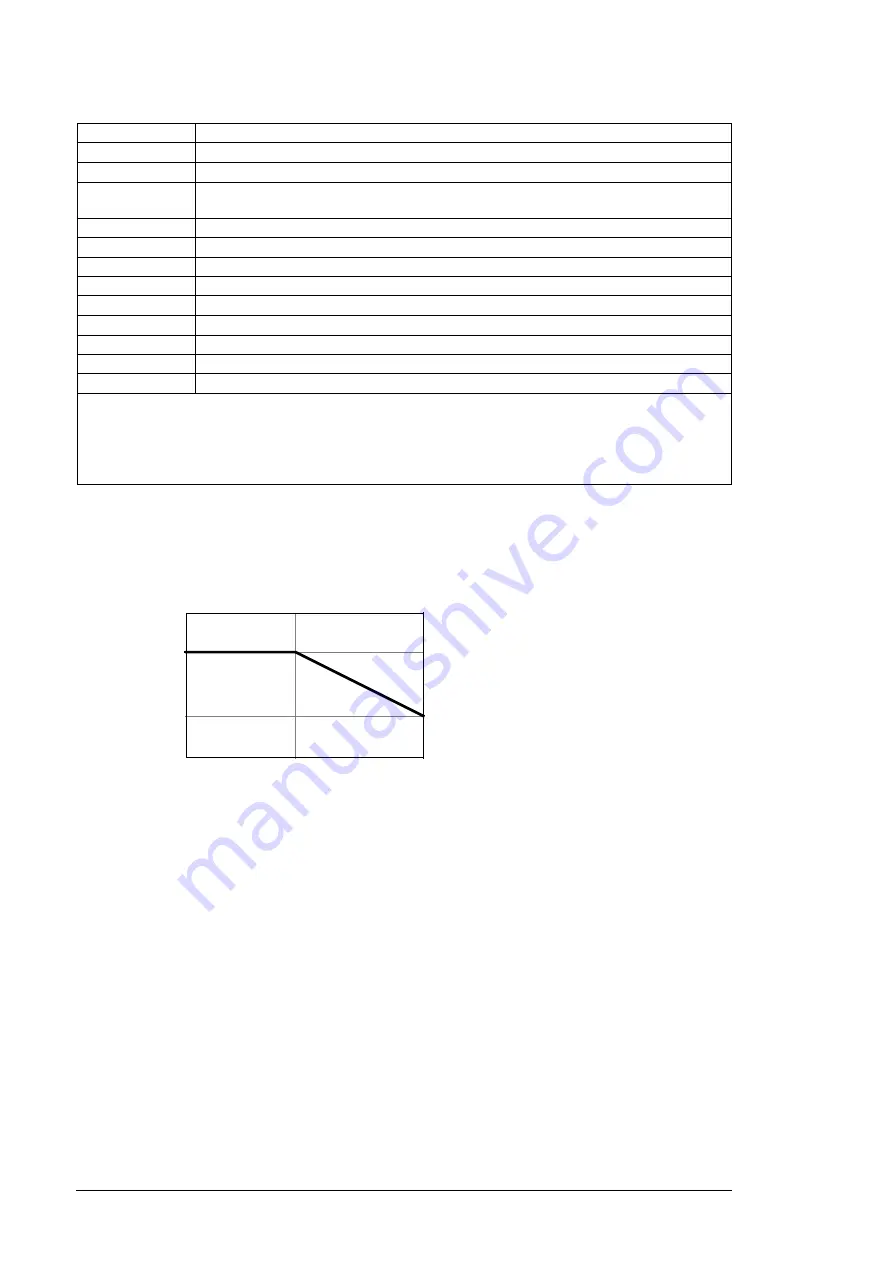
In the temperature range +40…50 °C (+104…122 °F), the rated output current is derated
by 1% for every added 1 °C (1.8 °F) as follows. Calculate the output current by multiplying
the current given in the rating table by the derating factor.
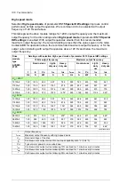
U
N
Nominal voltage of the drive
I
1N
Nominal input current (rms) at 40 °C (104 °F)
S
N
Apparent power (no overload)
I
max
Maximum output current. Available for 10 seconds at start, otherwise as long as allowed
by drive temperature. 140% … 200% of
I
Hd
, depending on power rating.
I
N
Continuous rms output current. No overload capability at 40 °C (104 °F)
P
N
Typical motor power in no-overload use.
I
Ld
Continuous rms output current allowing 10% overload for 1 minute every 5 minutes
P
Ld
Typical motor power for light-overload use.
I
Hd
Continuous rms output current allowing 50% overload for 1 minute every 5 minutes
*
Continuous rms output current allowing 30% overload for 1 minute every 5 minutes
**
Continuous rms output current allowing 25% overload for 1 minute every 5 minutes
***
Continuous rms output current allowing 40% overload for 1 minute every 5 minutes
P
Hd
Typical motor power for heavy-duty use.
Note:
To achieve the rated motor power given in the table, the rated current of the drive must be higher than
or equal to the rated motor current. The power ratings apply to most IEC 34 motors at the nominal voltage of
the drive.
We recommend to select the drive, motor and gear combination for the required motion profile with the
DriveSize dimensioning tool available from ABB.
Derating factor
Ambient temperature
1.00
0.90
+40 °C
+50 °C
+104 °F
+122 °F
0.80
Summary of Contents for ACS880-07XT Series
Page 1: ...ABB industrial drives Hardware manual ACS880 07XT drives 400 to 1200 kW ...
Page 4: ......
Page 12: ...12 ...
Page 20: ...20 Safety instructions ...
Page 26: ...26 Introduction to the manual ...
Page 54: ...54 Mechanical installation ...
Page 89: ...Electrical installation 89 PE 11 8 4 9 11 ...
Page 94: ...94 Electrical installation ...
Page 112: ...112 Fault tracing ...
Page 123: ...Maintenance 123 5 6 7 ...
Page 124: ...124 Maintenance 8 10 9 ...
Page 126: ...126 Maintenance 6 5 4 ...
Page 127: ...Maintenance 127 9 8 7 ...
Page 128: ...128 Maintenance 12 11 10 ...
Page 149: ...Dimensions 149 Dimension drawing examples Frame 2 R11 R10 with brake chopper ...
Page 150: ...150 Dimensions Frame 2 R11 R10 without brake chopper ...
Page 153: ...Dimensions 153 Location of input terminals ACS880 07XT 12 pulse ...
Page 154: ...154 Dimensions Location of output terminals ACS880 07XT R10 with du dt ...
Page 155: ...Dimensions 155 Location of output terminals ACS880 07XT R10 without du dt ...
Page 156: ...156 Dimensions Location of output terminals ACS880 07XT R11 with du dt ...
Page 157: ...Dimensions 157 Location of output terminals ACS880 07XT R11 without du dt ...
Page 158: ...158 Dimensions Location of PE terminals ACS880 07XT ...
Page 159: ...Dimensions 159 Location of resistor terminals ACS880 07XT R10 ...
Page 160: ...160 Dimensions Location of resistor terminals ACS880 07XT R11 ...
Page 168: ...www abb com drives www abb com drivespartners 3ABD00043579 Rev C EN 2018 01 01 Contact us ...


