


132 Maintenance
Reduced run
A “reduced run” function makes it possible to continue operation with one drive module if
the other module is out of service, for example, because of maintenance work. In principle,
reduced run is possible with only one module, but the physical requirements of operating
the motor still apply; the remaining module in use must be able to provide the motor with
enough magnetizing current.
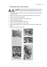
Starting reduced run operation
WARNING!
Obey the instructions in chapter
ignore them, injury or death, or damage to the equipment can occur.
1. Stop the drive and do the steps in section
Precautions before electrical work
before
you start the work.
2. If the control unit is powered from the faulty module, connect the control unit to
another 24 V DC power supply. We strongly recommend using an external power
supply with parallel-connected drive modules.
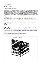
3. Disconnect all cables from the module to be serviced and remove it from its bay.
4. Switch on the power to the remaining drive module. Enter the number of drive
modules present into parameter 95.13 Reduced run mode.
5. Reset all faults and start the drive module. The maximum current is now automatically
limited according to the new drive module configuration. A mismatch between the
number of detected modules (95.14) and the value set in 95.13 will generate a fault.
6. If the STO function is in use, validate it.
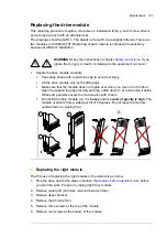
Resuming normal operation
1. Stop the drive and do the steps in section
Precautions before electrical work
before
you start the work.
2. Reinstall the module into its bay.
3. Connect all wires and fibres.
4. Switch on the power to the drive module package.
5. Enter “0” into parameter 95.13 Reduced run mode.
6. If the STO function is in use, validate it.
Summary of Contents for ACS880-07XT Series
Page 1: ...ABB industrial drives Hardware manual ACS880 07XT drives 400 to 1200 kW ...
Page 4: ......
Page 12: ...12 ...
Page 20: ...20 Safety instructions ...
Page 26: ...26 Introduction to the manual ...
Page 54: ...54 Mechanical installation ...
Page 89: ...Electrical installation 89 PE 11 8 4 9 11 ...
Page 94: ...94 Electrical installation ...
Page 112: ...112 Fault tracing ...
Page 123: ...Maintenance 123 5 6 7 ...
Page 124: ...124 Maintenance 8 10 9 ...
Page 126: ...126 Maintenance 6 5 4 ...
Page 127: ...Maintenance 127 9 8 7 ...
Page 128: ...128 Maintenance 12 11 10 ...
Page 149: ...Dimensions 149 Dimension drawing examples Frame 2 R11 R10 with brake chopper ...
Page 150: ...150 Dimensions Frame 2 R11 R10 without brake chopper ...
Page 153: ...Dimensions 153 Location of input terminals ACS880 07XT 12 pulse ...
Page 154: ...154 Dimensions Location of output terminals ACS880 07XT R10 with du dt ...
Page 155: ...Dimensions 155 Location of output terminals ACS880 07XT R10 without du dt ...
Page 156: ...156 Dimensions Location of output terminals ACS880 07XT R11 with du dt ...
Page 157: ...Dimensions 157 Location of output terminals ACS880 07XT R11 without du dt ...
Page 158: ...158 Dimensions Location of PE terminals ACS880 07XT ...
Page 159: ...Dimensions 159 Location of resistor terminals ACS880 07XT R10 ...
Page 160: ...160 Dimensions Location of resistor terminals ACS880 07XT R11 ...
Page 168: ...www abb com drives www abb com drivespartners 3ABD00043579 Rev C EN 2018 01 01 Contact us ...