


Guidelines for planning the electrical installation 59
The abbreviations used in the table are defined below.
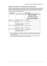
Non-ABB motors
Random
-wound
and
form-
wound
U
N
< 420 V
Standard:
Û
LL
= 1300 V
+ N or CMF
+ N + CMF
1)
420 V <
U
N
< 500 V
Standard:
Û
LL
= 1300 V
+ d
u
/d
t
+ (N or CMF)
+ N + d
u
/d
t
+ CMF
or
Reinforced:
Û
LL
= 1600 V,
0.2
microsecond
rise time
+ N or CMF
+ N + CMF
1)
500 V <
U
N
< 600 V
Reinforced:
Û
LL
= 1600 V
+ d
u
/d
t
+ (N or CMF)
+ N + d
u
/d
t
+ CMF
or
Reinforced:
Û
LL
= 1800 V
+ N or CMF
+ N + CMF
1)
600 V <
U
N
< 690 V
Reinforced:
Û
LL
= 1800 V
+ d
u
/d
t
+ N
+ N + d
u
/d
t
+ CMF
Reinforced:
Û
LL
= 2000 V,
0.3
microsecond
rise time ***
N + CMF
+ N + CMF
1)
*** If the intermediate DC circuit voltage of the drive is increased from the nominal level by resistor braking,
check with the motor manufacturer if additional output filters are needed in the applied drive operation
range.
1)
also d
u
/d
t
filter is required at the output of the basic drive modules if the motor cable length is less than
20 meters before connecting the motor cables together
Abbreviation
Definition
U
N
Nominal AC line voltage
Û
LL
Peak line-to-line voltage at motor terminals which the motor insulation must withstand
P
N
Motor nominal power
d
u
/d
t
d
u
/d
t
filter at the output of the drive
CMF
Common mode filter (E208)
N
N-end bearing (Insulated motor non-drive end bearing)
n.a.
Motors of this power range are not available as standard units. Consult the motor
manufacturer.
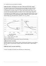
Motor
type
Nominal AC supply
voltage
Requirement for
Motor
insulation
system
ABB d
u
/d
t
and common mode filters, insulated N-end
motor bearings
100 kW <
P
N
<
350 kW
or
IEC 315 < frame size <
IEC 400
P
N
>
350 kW
or
frame size > IEC 400
134 hp <
P
N
<
469 hp
or
NEMA 500 < frame size <
NEMA 580
P
N
>
469 hp
or
frame size >
NEMA 580
Summary of Contents for ACS880-07XT Series
Page 1: ...ABB industrial drives Hardware manual ACS880 07XT drives 400 to 1200 kW ...
Page 4: ......
Page 12: ...12 ...
Page 20: ...20 Safety instructions ...
Page 26: ...26 Introduction to the manual ...
Page 54: ...54 Mechanical installation ...
Page 89: ...Electrical installation 89 PE 11 8 4 9 11 ...
Page 94: ...94 Electrical installation ...
Page 112: ...112 Fault tracing ...
Page 123: ...Maintenance 123 5 6 7 ...
Page 124: ...124 Maintenance 8 10 9 ...
Page 126: ...126 Maintenance 6 5 4 ...
Page 127: ...Maintenance 127 9 8 7 ...
Page 128: ...128 Maintenance 12 11 10 ...
Page 149: ...Dimensions 149 Dimension drawing examples Frame 2 R11 R10 with brake chopper ...
Page 150: ...150 Dimensions Frame 2 R11 R10 without brake chopper ...
Page 153: ...Dimensions 153 Location of input terminals ACS880 07XT 12 pulse ...
Page 154: ...154 Dimensions Location of output terminals ACS880 07XT R10 with du dt ...
Page 155: ...Dimensions 155 Location of output terminals ACS880 07XT R10 without du dt ...
Page 156: ...156 Dimensions Location of output terminals ACS880 07XT R11 with du dt ...
Page 157: ...Dimensions 157 Location of output terminals ACS880 07XT R11 without du dt ...
Page 158: ...158 Dimensions Location of PE terminals ACS880 07XT ...
Page 159: ...Dimensions 159 Location of resistor terminals ACS880 07XT R10 ...
Page 160: ...160 Dimensions Location of resistor terminals ACS880 07XT R11 ...
Page 168: ...www abb com drives www abb com drivespartners 3ABD00043579 Rev C EN 2018 01 01 Contact us ...