


Operation principle and hardware description 41
3
380…415 V AC. This is indicated in the type designation label as typical input voltage level
(3~ 400 V AC)
5
380…500 V AC. This is indicated in the type designation label as typical input voltage levels
(3~ 400/480/500 V AC)
7
525…690 V AC. This is indicated in the type designation label as typical input voltage levels
(3~ 525/600/690 V AC)
Option codes (plus codes)
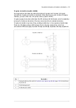
Supply connection
A004
12-pulse supply connection
Degree of protection
B054
IP42 (UL Type 1)
B055
IP54 (UL Type 12), pending
Resistor braking
D150
Brake choppers
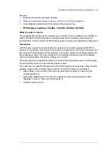
Filters
E200
EMC filter for second environment TN (grounded) system, category C3. Available for ACS880-
04XT-xxxx-7 types only
E201
EMC filter for second environment IT (ungrounded)) system, category C3. Available for ACS880-
04XT-xxxx-7 types only
E210
EMC filter for second environment TN (grounded) and IT (ungrounded)) systems, category C3.
Available for ACS880-04XT-xxxx-3 and -5 types only
E205
du/dt output filter
Line options
F250
Line contactor
Cabinet equipment
G300
Cabinet and module heating elements (external supply)
G307
Terminals for connecting external control voltage (230 V AC or 115 V AC, eg. UPS)
Motor cable options
H366
Common output for motor (need selE205)
Fieldbus adapters
K451
FDNA-01 DeviceNet™ adapter module
K454
FPBA-01 PROFIBUS DP adapter module
K457
FCAN-01 CANopen adapter module
K458
FSCA-01 RS-485 adapter module
K462
FCNA-01 ControlNet™ adapter module
K469
FECA-01 EtherCat adapter module
K470
FEPL-02 EtherPOWERLINK adapter module
K473
FENA-11 Ethernet adapter module for EtherNet/IP™, Modbus TCP and PROFINET IO protocols
K475
FENA-21 Ethernet adapter module for EtherNet/IP™, Modbus TCP and PROFINET IO protocols,
2-port
I/O extensions and feedback interfaces
L500
FIO-11 analog I/O extension module
L501
FIO-01 digital I/O extension module
L502
FEN-31 HTL incremental encoder interface module
L504
Additional I/O terminal block
L505
Thermistor relay (1 or 2 pcs)
L506
Pt100 relay (2, 3, 5 or 8 pcs)
CODE
DESCRIPTION
Summary of Contents for ACS880-07XT Series
Page 1: ...ABB industrial drives Hardware manual ACS880 07XT drives 400 to 1200 kW ...
Page 4: ......
Page 12: ...12 ...
Page 20: ...20 Safety instructions ...
Page 26: ...26 Introduction to the manual ...
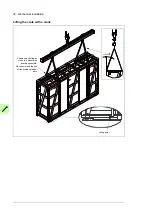
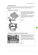
Page 54: ...54 Mechanical installation ...
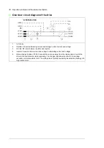
Page 89: ...Electrical installation 89 PE 11 8 4 9 11 ...
Page 94: ...94 Electrical installation ...
Page 112: ...112 Fault tracing ...
Page 123: ...Maintenance 123 5 6 7 ...
Page 124: ...124 Maintenance 8 10 9 ...
Page 126: ...126 Maintenance 6 5 4 ...
Page 127: ...Maintenance 127 9 8 7 ...
Page 128: ...128 Maintenance 12 11 10 ...
Page 149: ...Dimensions 149 Dimension drawing examples Frame 2 R11 R10 with brake chopper ...
Page 150: ...150 Dimensions Frame 2 R11 R10 without brake chopper ...
Page 153: ...Dimensions 153 Location of input terminals ACS880 07XT 12 pulse ...
Page 154: ...154 Dimensions Location of output terminals ACS880 07XT R10 with du dt ...
Page 155: ...Dimensions 155 Location of output terminals ACS880 07XT R10 without du dt ...
Page 156: ...156 Dimensions Location of output terminals ACS880 07XT R11 with du dt ...
Page 157: ...Dimensions 157 Location of output terminals ACS880 07XT R11 without du dt ...
Page 158: ...158 Dimensions Location of PE terminals ACS880 07XT ...
Page 159: ...Dimensions 159 Location of resistor terminals ACS880 07XT R10 ...
Page 160: ...160 Dimensions Location of resistor terminals ACS880 07XT R11 ...
Page 168: ...www abb com drives www abb com drivespartners 3ABD00043579 Rev C EN 2018 01 01 Contact us ...