100 Control units of the drive
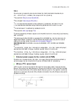
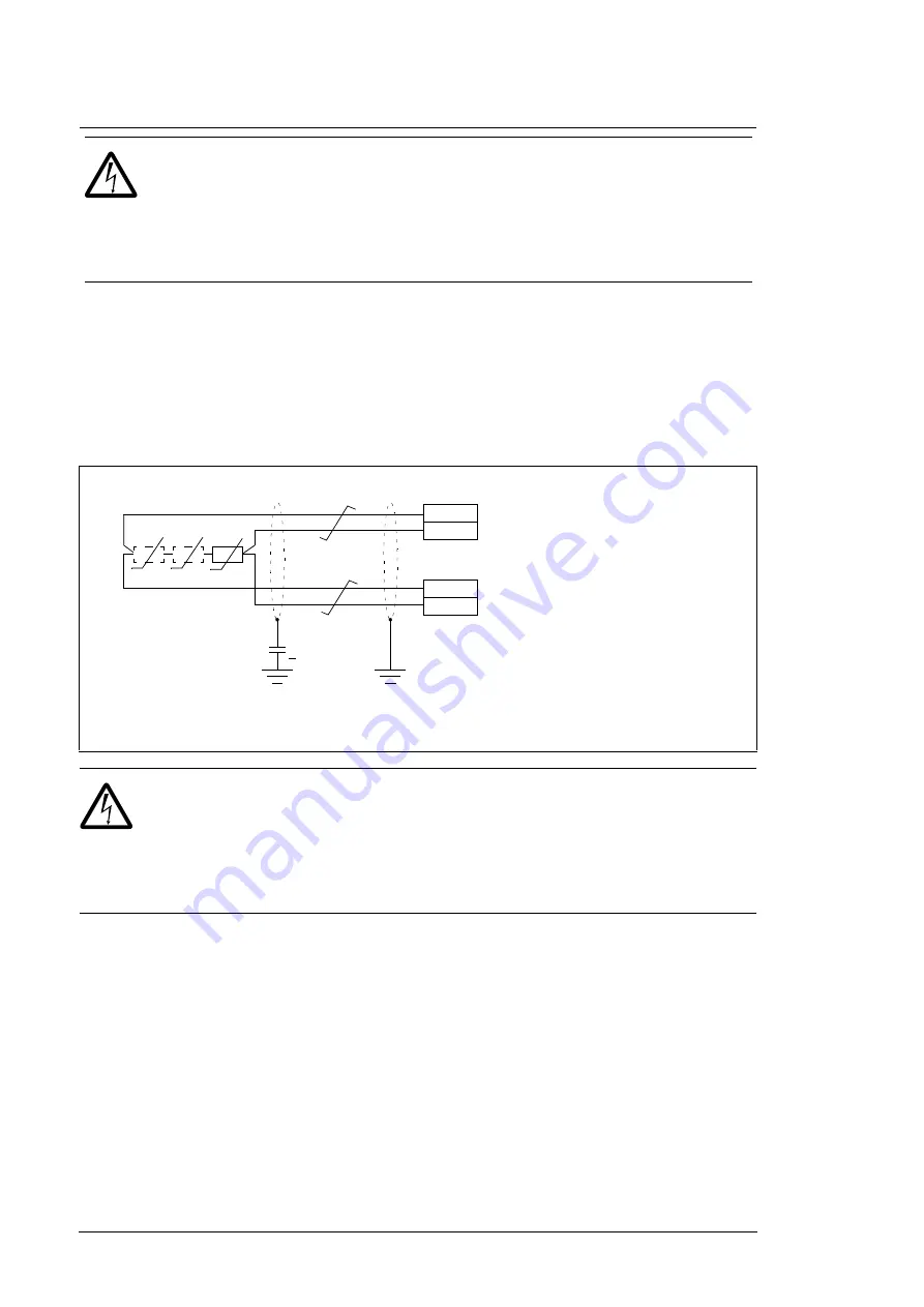
AI1 or AI2 as a Pt100, Pt1000 or KTY84 sensor input
Three Pt100/Pt1000 sensors or one KTY84 sensor for motor temperature measurement
can be connected between an analog input and output as shown below. (Alternatively, you
can connect the KTY to an FIO-11 or FAIO-01 analog I/O extension module or FEN-xx
encoder interface module.) Do not connect both ends of the cable shields directly to
ground. If a capacitor cannot be used at one end, leave that end of the shield
unconnected.
WARNING!
As the inputs pictured above are not insulated according to
IEC 60664, the connection of the motor temperature sensor requires double or
reinforced insulation between motor live parts and the sensor. If the assembly
does not fulfill the requirement, the I/O board terminals must be protected against contact
and must not be connected to other equipment or the temperature sensor must be isolated
from the I/O terminals.
DIIL input
On both the supply and inverter units, the DIIL input is used for the connection of safety
circuits. The input is parametrized to stop the unit when the input signal is lost.
Drive-to-drive link (XD2D)
The drive-to-drive link is a daisy-chained RS-485 transmission line that allows basic
master/follower communication with one master drive and multiple followers.
Enable bus termination on the inverters at the ends of the drive-to-drive link by setting
switch D2D TERM on the control unit to ON. On intermediate inverters, disable bus
termination.
Use shielded twisted-pair cable (~100 ohm, for example, PROFIBUS-compatible cable) for
the wiring. For best immunity, high quality cable is recommended. Keep the cable as short
WARNING!
As the inputs pictured above are not insulated according to
IEC 60664, the connection of the motor temperature sensor requires double or
reinforced insulation between motor live parts and the sensor. If the assembly
does not fulfill the requirement, the I/O board terminals must be protected against contact
and must not be connected to other equipment or the temperature sensor must be
isolated from the I/O terminals.
1) For AI1, set input type to voltage with switch AI1. For AI2, set input type with switch AI2. Set the
appropriate analog input unit to V (volt) in parameter group
12 Standard AI
.
2) Select the excitation mode in parameter group
13 Standard AO
.
1…3 × Pt100/Pt1000/PTC or 1 × KTY84
3.3 nF
> 630 V AC
XAI
XAO
AIn+
AIn-
AOn
AGND
1)
2)
T
T
T
Summary of Contents for ACS880-07XT Series
Page 1: ...ABB industrial drives Hardware manual ACS880 07XT drives 400 to 1200 kW ...
Page 4: ......
Page 12: ...12 ...
Page 20: ...20 Safety instructions ...
Page 26: ...26 Introduction to the manual ...
Page 54: ...54 Mechanical installation ...
Page 89: ...Electrical installation 89 PE 11 8 4 9 11 ...
Page 94: ...94 Electrical installation ...
Page 112: ...112 Fault tracing ...
Page 123: ...Maintenance 123 5 6 7 ...
Page 124: ...124 Maintenance 8 10 9 ...
Page 126: ...126 Maintenance 6 5 4 ...
Page 127: ...Maintenance 127 9 8 7 ...
Page 128: ...128 Maintenance 12 11 10 ...
Page 149: ...Dimensions 149 Dimension drawing examples Frame 2 R11 R10 with brake chopper ...
Page 150: ...150 Dimensions Frame 2 R11 R10 without brake chopper ...
Page 153: ...Dimensions 153 Location of input terminals ACS880 07XT 12 pulse ...
Page 154: ...154 Dimensions Location of output terminals ACS880 07XT R10 with du dt ...
Page 155: ...Dimensions 155 Location of output terminals ACS880 07XT R10 without du dt ...
Page 156: ...156 Dimensions Location of output terminals ACS880 07XT R11 with du dt ...
Page 157: ...Dimensions 157 Location of output terminals ACS880 07XT R11 without du dt ...
Page 158: ...158 Dimensions Location of PE terminals ACS880 07XT ...
Page 159: ...Dimensions 159 Location of resistor terminals ACS880 07XT R10 ...
Page 160: ...160 Dimensions Location of resistor terminals ACS880 07XT R11 ...
Page 168: ...www abb com drives www abb com drivespartners 3ABD00043579 Rev C EN 2018 01 01 Contact us ...

