Section 3 CCF Displays
Alarm Detection
3BUR002418-600 A
59
Alarm Detection
PID loops detect alarms on the measured variable, setpoint, deviations, and output.
Control loops (Auto/Manual for example) detect alarms on the measured variable
and output. Continuous loops (indicator and calculator for example) detect alarms
on the measured variable.
Measured variable alarms are trip points. Setpoint and output alarms are limit
alarms on their high or low value. Deviation alarms compare the difference between
the measured variable (going into the PID FCM) and the setpoint. A high deviation
occurs when the measured variable of the PID FCM is above the setpoint by the
limit amount. The deviation value is never limited by the system.
The input and output rate alarms compare the number of engineering units set as the
limit to the actual change in one loop cycle.
Discrete loops detect device related alarms. The device alarms are:
•
ILLEGAL (Illegal State or Command). The system can read the feedback from
the device, but no state is defined for the feedback bit combination or Systems
recognize the command from the operator or the TCL program, but it is an
invalid command as defined by the Device Descriptor Templet.
•
ABNORMAL (Abnormal State Change). The device changed state, but no
command to do so was issued. Abnormal State Change alarms will not occur if
the state changes to match DEV_CMND.
•
TRANSITION (Unknown State or Timeout). The system cannot read the
feedback from the device or the system sent a valid command to the device, but
the device did not respond within the specified time.
•
STATE (State Alarm). The device has entered a state defined by the device
descriptor set as an alarm state for the device.
Alarm Indication and Viewing
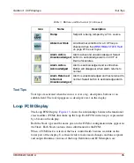
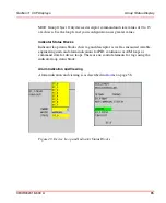
Alarm priority is indicated using colored backgrounds and the characters H (high),
L (low), D (Deviation), R (Rate) and ? (Bad data quality) in front of the display
value. The background color of the highest priority alarm currently active is
displayed. An unacknowledged alarm blinks. On faceplates, an Alarm
Acknowledge button appears when an unacknowledged alarm exists. Indications are
also made for Active Alarm Acknowledged and Inactive Alarm Unacknowledged.
Summary of Contents for Ability 800xA Series
Page 1: ...Power and productivity for a better worldTM 800xA for MOD 300 Operation System Version 6 0 ...
Page 2: ......
Page 3: ...800xA for MOD 300 Operation System Version 6 0 ...
Page 14: ...Table of Contents 14 3BUR002418 600 A ...
Page 74: ...Area Graphic Display Section 3 CCF Displays 74 3BUR002418 600 A ...
Page 102: ...Batch Connectivity to M0D 300 Section 4 TCL Displays 102 3BUR002418 600 A ...
Page 120: ...TLL Messages Section 5 TLL Displays 120 3BUR002418 600 A ...
Page 212: ...Viewing Abnormal State on MOD Loop Displays Section 8 Operation Examples 212 3BUR002418 600 A ...
Page 320: ...BRKPTS Appendix A Runtime Templates 320 3BUR002418 600 A ...
Page 322: ...Updates in Revision Index A 322 3BUR002418 600 A ...
Page 330: ...Index 330 3BUR002418 600 A ...
Page 331: ......

