


AI835
Appendix A Runtime Templates
294
3BUR002418-600 A
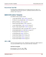
The default entry is 0 (zero)
LABEL
Enter a characteristic name to identify the AI835 Module of the station. The name
may contain up to 20 characters.
POSITION
Enter a number from 1 to 12 representing the position of the I/O module relative to
the FCI. The I/O module directly next to the FCI is number 1.
Default value is 1.
POWER LINE FREQUENCY
Enter the power line frequency to filter out (notch) the signal.
The valid values are:
16, 50, and 60.
The default value is 60.
REPORT FAULTS 01 through 08
If channel faults are to be reported, enter a
YES
; if not enter a
NO
.
The default value is YES.
RESERVED OPTIONS
This field reserved for future use. A zero (0) should be entered as a default value.
TC TYPE 01 through 08
Enter the type of sensor that will be connected to each channel. When channel 08
serves as the Cold Junction Compensation value, enter the sensor type, normally
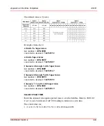
If positions are to be used for spare MTUs, the spares must be in place so the rest
of the I/O modules are numbered correctly. The spare MTU will use a position
number when it is on the ModuleBus.
Summary of Contents for Ability 800xA Series
Page 1: ...Power and productivity for a better worldTM 800xA for MOD 300 Operation System Version 6 0 ...
Page 2: ......
Page 3: ...800xA for MOD 300 Operation System Version 6 0 ...
Page 14: ...Table of Contents 14 3BUR002418 600 A ...
Page 74: ...Area Graphic Display Section 3 CCF Displays 74 3BUR002418 600 A ...
Page 102: ...Batch Connectivity to M0D 300 Section 4 TCL Displays 102 3BUR002418 600 A ...
Page 120: ...TLL Messages Section 5 TLL Displays 120 3BUR002418 600 A ...
Page 212: ...Viewing Abnormal State on MOD Loop Displays Section 8 Operation Examples 212 3BUR002418 600 A ...
Page 320: ...BRKPTS Appendix A Runtime Templates 320 3BUR002418 600 A ...
Page 322: ...Updates in Revision Index A 322 3BUR002418 600 A ...
Page 330: ...Index 330 3BUR002418 600 A ...
Page 331: ......


