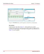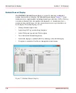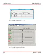
TRIO Block Display
Section 7 I/O Displays
188
3BUR002418-600 A
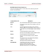
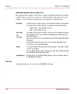
TRIO Block I/O Area
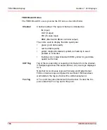
The TRIO Block I/O area represents the I/O data as described below.
Channel
Channel number. The type of channel is indicated as:
IN (Input)
OUT (Output)
TRI (Tri state Input)
BSM (Bus Switch Block controller output)
The colors used to display the data quality are:
•
green: good data quality
•
red: bad data quality
•
yellow: diagnostic cleared, system is checking to see if
problem is corrected
•
flashing color: value forced with HHM, yellow for good data
quality, red for bad
CCF Tag
Tag of the loop sending or receiving information from the channel.
If multiple tags access the same channel, only one tag is displayed
for it.
Note that for continuous loops with Analog and Digital Output
FCMs or device loops configured for warmstart that have been
warmstarted, the tag is shown with a white background.
TLL Tag
A TLL point may also interact with the channel. To view the TLL
point, select the TLL Tag cell for the point.
Summary of Contents for Ability 800xA Series
Page 1: ...Power and productivity for a better worldTM 800xA for MOD 300 Operation System Version 6 0 ...
Page 2: ......
Page 3: ...800xA for MOD 300 Operation System Version 6 0 ...
Page 14: ...Table of Contents 14 3BUR002418 600 A ...
Page 74: ...Area Graphic Display Section 3 CCF Displays 74 3BUR002418 600 A ...
Page 102: ...Batch Connectivity to M0D 300 Section 4 TCL Displays 102 3BUR002418 600 A ...
Page 120: ...TLL Messages Section 5 TLL Displays 120 3BUR002418 600 A ...
Page 212: ...Viewing Abnormal State on MOD Loop Displays Section 8 Operation Examples 212 3BUR002418 600 A ...
Page 320: ...BRKPTS Appendix A Runtime Templates 320 3BUR002418 600 A ...
Page 322: ...Updates in Revision Index A 322 3BUR002418 600 A ...
Page 330: ...Index 330 3BUR002418 600 A ...
Page 331: ......

