Section 8 Operation Examples
Viewing Alarms on MOD Loop Displays
3BUR002418-600 A
209
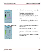
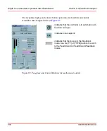
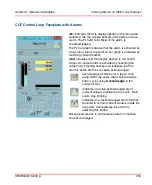
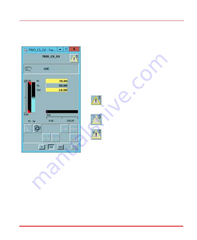
CCF Control Loop Faceplate with Alarms
[
Pv
] indicates that this display applies to the measured
variable while the colored background shows an active
alarm. The Pv field color blinks if the alarm is
unacknowledged.
The Pv bar graph indicates that the alarm is activated by
a high input. Alarm trip point on bar graph is indicated by
matching colored marker.
[
Out
] indicates that this display applies to the control
output. An output alarm is activated by reaching the
output limit. Flashing background indicates that the
alarm is active and has not been acknowledged.
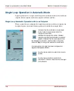
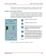
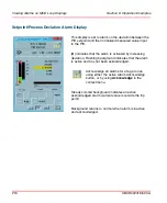
Acknowledge all alarms for a tag at once
using either the active Alarm Acknowledge
button, or by using
Acknowledge
in the
context menu.
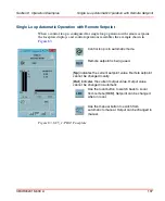
Indicates an active acknowledged alarm
(current value is outside the trip point). Field
colors stop blinking.
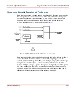
Indicates an unacknowledged alarm that has
returned to normal (current value is inside the
trip point). Acknowledge the alarm by
selecting this button.
Background returns to normal when alarm is inactive
and acknowledged.
Summary of Contents for Ability 800xA Series
Page 1: ...Power and productivity for a better worldTM 800xA for MOD 300 Operation System Version 6 0 ...
Page 2: ......
Page 3: ...800xA for MOD 300 Operation System Version 6 0 ...
Page 14: ...Table of Contents 14 3BUR002418 600 A ...
Page 74: ...Area Graphic Display Section 3 CCF Displays 74 3BUR002418 600 A ...
Page 102: ...Batch Connectivity to M0D 300 Section 4 TCL Displays 102 3BUR002418 600 A ...
Page 120: ...TLL Messages Section 5 TLL Displays 120 3BUR002418 600 A ...
Page 212: ...Viewing Abnormal State on MOD Loop Displays Section 8 Operation Examples 212 3BUR002418 600 A ...
Page 320: ...BRKPTS Appendix A Runtime Templates 320 3BUR002418 600 A ...
Page 322: ...Updates in Revision Index A 322 3BUR002418 600 A ...
Page 330: ...Index 330 3BUR002418 600 A ...
Page 331: ......

