


Appendix A Runtime Templates
DO820
3BUR002418-600 A
317
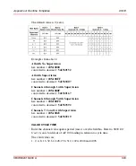
OSP VALUE 01 through 08
Enter the channel value (0 or 1) to output after an OSP TIMEOUT. If the OSP
HOLD has been selected as the OSP value then this field entry is ignored.
The valid values are:
0 or 1.
Where 0 = off and 1 = on.
The default is 0.
POSITION
Enter a number from 1 to 12 representing the position of the I/O module relative to
the FCI. The I/O module directly next to the FCI is number 1.
Default value is 1.
REPORT FAULTS 01 through 08
If channel faults are to be reported, enter a
YES
;
if not enter a
NO
.
The default value is YES.
RESERVED OPTIONS
This field reserved for future use. A zero (0) should be entered as a default value.
VALUE CYCLE TIME
Enter the channel value update period (msec) over the fieldbus. Refer to
S800 I/O
User’s Guide
for details of AF 100 loading in relation to cycle time.
The valid values are:
1, 2, 4, 8, 16, 32, 64, 128, 256, 512, 1024, 2048 and 4096.
The default value is 128.
Summary of Contents for Ability 800xA Series
Page 1: ...Power and productivity for a better worldTM 800xA for MOD 300 Operation System Version 6 0 ...
Page 2: ......
Page 3: ...800xA for MOD 300 Operation System Version 6 0 ...
Page 14: ...Table of Contents 14 3BUR002418 600 A ...
Page 74: ...Area Graphic Display Section 3 CCF Displays 74 3BUR002418 600 A ...
Page 102: ...Batch Connectivity to M0D 300 Section 4 TCL Displays 102 3BUR002418 600 A ...
Page 120: ...TLL Messages Section 5 TLL Displays 120 3BUR002418 600 A ...
Page 212: ...Viewing Abnormal State on MOD Loop Displays Section 8 Operation Examples 212 3BUR002418 600 A ...
Page 320: ...BRKPTS Appendix A Runtime Templates 320 3BUR002418 600 A ...
Page 322: ...Updates in Revision Index A 322 3BUR002418 600 A ...
Page 330: ...Index 330 3BUR002418 600 A ...
Page 331: ......


