background image

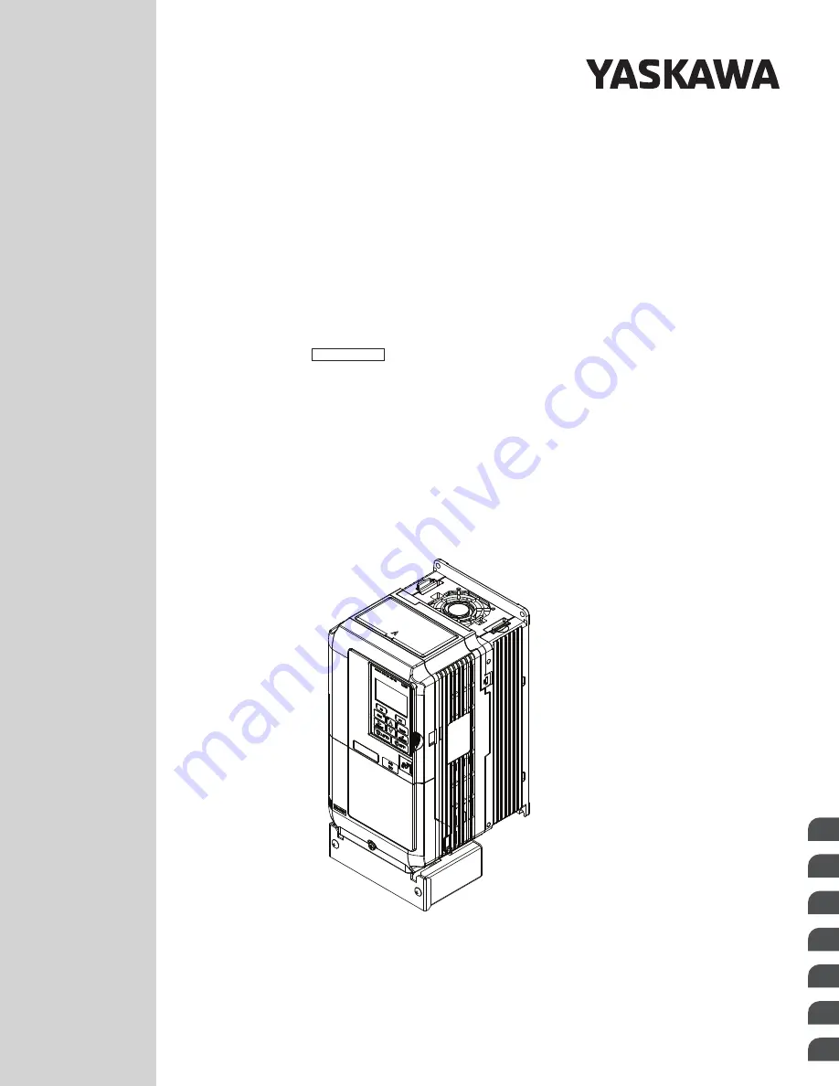
YASKAWA AC Drive Z1000

MANUAL NO.   SIEP YAIZ1U 03B

AC Drive for HVAC Fan and Pump 

Programming Manual

Models: 600 V Class: 2 to 250 HP

To properly use the product, read this manual thoroughly and retain 

for easy reference, inspection, and maintenance. Ensure the end user 

receives this manual.

Type: CIMR-ZU

Parameter Details

1

Periodic Inspection &

Maintenance

2

Parameter List

A

BACnet Communications

B

APOGEE FLN (P1)

Communications

C

Metasys N2

Communications

D

MEMOBUS/Modbus

Communications

E

Summary of Contents for Z1000 CIMR-ZU*A Series

Page 1: ...y use the product read this manual thoroughly and retain for easy reference inspection and maintenance Ensure the end user receives this manual Type CIMR ZU Parameter Details 1 Periodic Inspection Maintenance 2 Parameter List A BACnet Communications B APOGEE FLN P1 Communications C Metasys N2 Communications D MEMOBUS Modbus Communications E ...

Page 2: ...ent liability is assumed with respect to the use of the information contained herein Moreover because Yaskawa is constantly striving to improve its high quality products the information contained in this manual is subject to change without notice Every precaution has been taken in the preparation of this manual Yaskawa assumes no responsibility for errors or omissions Neither is any liability assu...

Page 3: ... 31 b4 Timer Function 36 b5 PI Control 37 b8 Energy Saving 49 1 3 C Tuning 51 C1 Acceleration and Deceleration Times 51 C2 S Curve Characteristics 52 C4 Torque Compensation 53 C6 Carrier Frequency 54 Rated Current Depending on Carrier Frequency 55 1 4 d Reference Settings 56 d1 Frequency Reference 56 d2 Frequency Upper Lower Limits 57 d3 Jump Frequency 58 d4 Frequency Reference Hold and Up Down 2 ...

Page 4: ...10 o Operator Related Settings 128 o1 HOA Keypad Display Selection 128 o2 HOA Keypad Functions 131 o3 Copy Function 132 o4 Maintenance Monitor Settings 133 1 11 S Special Parameters 135 S1 Dynamic Audible Noise Control Function 135 S2 Sequence Timers 136 S3 Secondary PI PI2 Control 140 S4 Bypass Operation 144 S5 HOA Keypad Parameters 150 S6 Phase Order Selections 153 1 12 T Motor Tuning 154 T1 Par...

Page 5: ...2 Parameter Groups 185 A 3 A Initialization Parameters 186 A1 Initialization 186 A2 User Parameters 186 A 4 b Application 187 b1 Operation Mode Selection 187 b2 DC Injection Braking and Short Circuit Braking 187 b3 Speed Search 188 b4 Timer Function 189 b5 PI Control 189 b8 Energy Saving 192 A 5 C Tuning 193 C1 Acceleration and Deceleration Times 193 C2 S Curve Characteristics 193 C4 Torque Compen...

Page 6: ...eypad Functions 222 o3 Copy Function 223 o4 Maintenance Monitor Settings 223 A 13 S Special Application 224 S1 Dynamic Noise Control Function 224 S2 Sequence Timers 224 S3 Secondary PI PI2 Control 226 S4 Bypass Operation 228 S5 HOA Keypad Parameters 228 S6 Z1000 Protection 229 A 14 T Motor Tuning 230 T1 Induction Motor Auto Tuning 230 T2 PM Motor Auto Tuning 230 A 15 U Monitors 232 U1 Operation St...

Page 7: ...ters and the Enter Command 261 Reading Drive Parameters 261 Writing Drive Parameters 261 Enter Command 261 B 9 Communication Errors 262 B 10 Self Diagnostics 263 B 11 BACnet Protocol Implementation Conformance Statement 264 C APOGEE FLN P1 COMMUNICATIONS 267 C 1 APOGEE FLN Set Up 268 C 2 Communication Specifications 269 C 3 Connecting to a Network 270 Network Cable Connection 270 Wiring Diagram fo...

Page 8: ... Metasys N2 Analog Output AO Summary 297 Metasys N2 Binary Input BI Summary 297 Metasys N2 Binary Output BO Summary 298 D 8 Mailbox Function 299 Reading Drive Parameters 299 Writing Drive Parameters 299 D 9 Self Diagnostics 300 E MEMOBUS MODBUS COMMUNICATIONS 301 E 1 MEMOBUS Modbus Configuration 302 E 2 Communication Specifications 303 E 3 Connecting to a Network 304 Network Cable Connection 304 W...

Page 9: ...odbus Data Table 316 Command Data 316 Monitor Data 317 Broadcast Messages 325 Fault Trace Contents 325 Alarm Register Contents 327 E 10 Enter Command 328 Enter Command Types 328 E 11 Communication Errors 329 MEMOBUS Modbus Error Codes 329 Slave Not Responding 329 E 12 Self Diagnostics 330 INDEX 331 Table of Contents YASKAWA SIEP YAIZ1U 03B YASKAWA AC Drive Z1000 Programming Manual 9 ...

Page 10: ...Table of Contents This Page Intentionally Blank 10 YASKAWA SIEP YAIZ1U 03B YASKAWA AC Drive Z1000 Programming Manual ...

Page 11: ...his product that if not heeded may result in fatality personal injury or equipment damage Yaskawa is not responsible for the consequences of ignoring these instructions i 1 PREFACE 12 i 2 GENERAL SAFETY 14 i YASKAWA SIEP YAIZ1U 03B YASKAWA AC Drive Z1000 Programming Manual 11 ...

Page 12: ...agram main circuit and control circuit connections switch and jumper configuration basic troubleshooting standards compliance and fusing drive specifications and an abbreviated parameter list Z1000 Series AC Drive Programming Manual 600 V Models SIEPYAIZ1U03 This manual provides detailed information on parameter settings drive functions maintenance and MEMOBUS Modbus specifications Use this manual...

Page 13: ...an Society of Heating Refrigerating and Air Conditioning Engineers ASHRAE GPD is a trademark of Yaskawa Inc Metasys N2 is a trademark of Johnson Controls Inc MODBUS is a registered trademark of Schneider Automation Inc Other companies and product names mentioned in this manual are trademarks of those companies i 1 Preface YASKAWA SIEP YAIZ1U 03B YASKAWA AC Drive Z1000 Programming Manual 13 ...

Page 14: ...ffice WARNING Read and understand this manual before installing operating or servicing this drive The drive must be installed according to this manual and local codes The following conventions are used to indicate safety messages in this manual Failure to heed these messages could result in serious or fatal injury or damage to the products or to related equipment and systems DANGER Indicates a haz...

Page 15: ...modification of the product made by the user This product must not be modified Do not allow unqualified personnel to use equipment Failure to comply could result in death or serious injury Maintenance inspection and replacement of parts must be performed only by authorized personnel familiar with installation adjustment and maintenance of AC drives Do not remove covers or touch circuit boards whil...

Page 16: ...d circuit boards Failure to comply may result in ESD damage to the drive circuitry Do not perform a withstand voltage test or megger test on any part of the drive Failure to comply could result in damage to the sensitive devices within the drive Do not operate damaged equipment Failure to comply could result in further damage to the equipment Do not connect or operate any equipment with visible da...

Page 17: ... PARAMETERS 62 1 6 F OPTION SETTINGS 70 1 7 H TERMINAL FUNCTIONS 72 1 8 L PROTECTION FUNCTIONS 99 1 9 N SPECIAL ADJUSTMENTS 123 1 10 O OPERATOR RELATED SETTINGS 128 1 11 S SPECIAL PARAMETERS 135 1 12 T MOTOR TUNING 154 1 13 U MONITOR PARAMETERS 158 1 YASKAWA SIEP YAIZ1U 03B YASKAWA AC Drive Z1000 Programming Manual 17 ...

Page 18: ...up Mode Verify Mode and Auto Tuning Mode cannot be accessed Setting 2 Advanced Access Level A All parameters can be viewed and edited Notes on Parameter Access If the drive parameters are password protected by A1 04 and A1 05 parameters A1 01 through A1 03 A1 07 and A2 01 through A2 32 cannot be modified If a digital input terminal programmed for Program lockout H1 oo 1B is enabled parameter value...

Page 19: ...ence on page 73 for more information on digital input functions Setting 3410 HVAC Initialization Resets parameters to default settings The following parameters are not reset H1 03 b1 Customer Safeties H1 04 b2 BAS Interlock H1 05 AF Emergency Override Forward Run H2 03 b2 BAS Interlock Relay Contact Note After performing an HVAC Initialization H1 03 to H1 05 and H2 03 will be displayed in the Modi...

Page 20: ...A1 01 A1 02 A1 03 A1 06 and A2 01 through A2 33 The instructions below demonstrate how to set password 1234 An explanation follows on how to enter that password to unlock the parameters Table 1 2 Setting the Password for Parameter Lock Step Display Result 1 Turn on the power to the drive The initial display appears MODE U1 01 0 00Hz U1 02 0 00Hz U1 03 0 00 A DRV Freq Ref AI Rdy FWD LSEQ LREF 2 Pre...

Page 21: ...HELP MODE PRG DATA Programming FWD Table 1 4 Enter the Password to Unlock Parameters continuing from step 3 above Step Display Result 1 Press to enter the parameter setup display PRMSET Initialization Select Language PRG A1 00 0 FWD 2 Press F1 F2 to select the flashing digits as shown PRMSET Select Language English PRG FWD A1 00 0 0 3 Press to scroll to A1 04 and PRMSET A1 04 0 0 9999 0 PRG Enter ...

Page 22: ...dition the parameters most likely to be changed are assigned to the group of User Parameters A2 01 through A2 16 User Parameters are part of the Setup Group which provides quicker access by eliminating the need to scroll through multiple menus u A2 User Parameters n A2 01 to A2 32 User Parameters 1 to 32 The user can select up to 32 parameters and assign them to parameters A2 01 through A2 32 to p...

Page 23: ...ser Parameter group Setting 1 Save list of recently edited parameters Set A2 33 to 1 to automatically save recently edited parameters to A2 17 through A2 32 A total of 16 parameters are saved with the most recently edited parameter set to A2 17 the second most recently to A2 18 and so on Access the User Parameters using the Setup Mode of the HOA keypad Note User parameters are listed from A2 27 to...

Page 24: ...two analog input terminals Make the settings as described in Table 1 5 for the input used Table 1 5 Analog Input Settings for Frequency Reference Using Voltage Signals Terminal Signal Level Parameter Settings Notes Signal Level Selection Function Selection Gain Bias A1 0 to 10 V with Zero Limit H3 01 0 H3 02 0 Frequency Reference Bias H3 03 H3 04 Set Jumper S1 on the terminal board to V for voltag...

Page 25: ...mmunications port control terminals R R S and S Refer to MEMOBUS Modbus Configuration on page 302 for instructions Setting 3 Option Card This setting requires entering the frequency reference via an option board plugged into connector CN5 on the drive control board Consult the option card manual for instructions on integrating the drive with the communication system Note If the frequency reference...

Page 26: ...ration time The default deceleration time is set to parameter C1 02 When the output frequency falls below the level set in parameter b2 01 the drive will start DC injection or Zero Speed Control depending on the selected control mode Setting 1 Coast to Stop When the Run command is removed the drive will shut off its output and the motor will coast uncontrolled deceleration to stop The stopping tim...

Page 27: ...If an overcurrent oC fault occurs during DC Injection Braking to Stop increase the momentary power loss minimum baseblock time L2 03 until the fault no longer occurs Setting 3 Coast with Timer When the Run command is removed the drive will turn off its output and the motor will coast to stop The drive will not start if a Run command is input before the time t C1 02 has expired Cycle the Run comman...

Page 28: ...n while in Programming Mode No Parameter Name Setting Range Default b1 08 Run Command Selection in Programming Mode 0 to 2 0 Setting 0 Run Command Is Not Accepted in Programming Mode A Run command is not accepted while the HOA keypad is in Programming Mode Setting 1 Run Command Is Accepted in Programming Mode A Run command is accepted in any HOA keypad mode Setting 2 Prohibit Entering Programming ...

Page 29: ...tures n b2 01 DC Injection Braking Start Frequency Active when Ramp to Stop is selected as the stopping method b1 03 0 No Name Setting Range Default b2 01 DC Injection Braking Start Frequency 0 0 to 10 0 Hz Determined by A1 02 The function triggered by parameter b2 01 depends on the control mode that has been selected V f A1 02 0 For these control modes parameter b2 01 sets the starting frequency ...

Page 30: ...ffect use DC Injection or Speed Search to stop the motor or detect motor speed before starting it Otherwise motor stalling and other faults can occur n b2 04 DC Injection Braking Time at Stop Sets the time of DC Injection Braking at stop Used to completely stop a motor with high inertia load after ramp down Increase the value if the motor still coasts by inertia after it should have stopped Disabl...

Page 31: ... Speed Search b3 24 0 Current Detection Speed Search detects the motor speed by looking at motor current in IM motors When Speed Search is started it reduces the output frequency starting from either the maximum output frequency or the frequency reference while increasing the output voltage using the time set in parameter L2 04 As long as the current is higher than the level set to b3 02 the outpu...

Page 32: ... drive estimates the motor speed by analyzing the back EMF voltage and outputs the estimated frequency and increases the voltage using the time constant set in parameter L2 04 After that the motor is accelerated or decelerated to the frequency reference starting from the detected speed If there is not enough residual voltage in the motor windings to perform the calculations described above the dri...

Page 33: ...rotation of these smaller motors in which case Speed Estimation would stop the motor Use Short Circuit Braking instead of Speed Search when using OLV PM with a long motor cable Use Short Circuit Braking instead of Speed Search when attempting to find the speed of a motor coasting faster than 200 Hz in OLV PM n Speed Search Activation Speed Search can be activated using any of the methods 1 through...

Page 34: ...need to change this setting Lower this value if the drive has trouble restarting No Name Setting Range Default b3 02 Speed Search Deactivation Current 0 to 200 Determined by A1 02 Note When parameter A1 02 0 V f Control the factory default setting is 120 n b3 03 Speed Search Deceleration Time Sets the output frequency reduction ramp used by the Current Injection Method of Speed Estimation b3 24 1 ...

Page 35: ... Speed Search Selection Speed Estimation Type Sets how the drive determines the motor rotation direction when performing Speed Estimation Speed Search No Parameter Name Setting Range Default b3 14 Bi Directional Speed Search Selection 0 1 1 Setting 0 Disabled The drive uses the frequency reference to determine the direction of motor rotation to restart the motor Setting 1 Enabled The drive detects...

Page 36: ... Selection when Run Command is Given during Uv Activates and deactivates Speed Search at start in accordance with whether a Run command was issued during an undervoltage Uv condition Function is active when a momentary power loss L2 01 1 or 2 Speed Search at start b3 01 1 and coasting to a stop b1 03 1 are enabled No Name Setting Range Default b3 33 Speed Search Selection when Run Command is Given...

Page 37: ...gral of the deviation It minimizes the offset between target and feedback value that typically remains when pure P control is used The integral time I time constant determines how fast the offset is eliminated n PI Operation To better demonstrate PI functionality the diagram below illustrates how the PI output changes when the PI input deviation jumps from 0 to a constant level PI input I control ...

Page 38: ...nput two feedback signals for controlling a differential process value Normal PI Feedback Input the PI feedback signal from one of the sources listed below Table 1 9 PI Feedback Sources PI Feedback Source Settings Analog Input A1 Set H3 02 B Analog Input A2 Set H3 10 B Note A duplicate allocation of the PI feedback input will cause an oPE alarm Differential Feedback The second PI feedback signal f...

Page 39: ...n PI Block Diagram Figure 1 16 PI Block Diagram 1 2 b Application YASKAWA SIEP YAIZ1U 03B YASKAWA AC Drive Z1000 Programming Manual 39 1 Parameter Details ...

Page 40: ... 04 Integral Limit Setting Sets the maximum output possible from the integral block as a percentage of the maximum frequency E1 04 No Name Setting Range Default b5 04 Integral Limit Setting 0 0 to 100 0 100 0 Note On some applications especially those with rapidly varying loads the output of the PI function may show a fair amount of oscillation Program b5 04 to apply a limit to the integral output...

Page 41: ...Default b5 11 PI Output Reverse Selection 0 1 0 Setting 0 Reverse Disabled Negative PI output will be limited to 0 and the drive output will be stopped Setting 1 Reverse Enabled Negative PI output will cause the drive to run in the opposite direction n PI Feedback Loss Detection The PI feedback loss detection function detects broken sensors or broken sensor wiring It should be used when PI control...

Page 42: ...ion range Detection remains active when PI is disabled by digital input H1 oo 19 Setting 2 Feedback Loss Fault Remains active when PI is disabled by digital input If the PI feedback value falls below the level set to b5 13 for longer than the time set to b5 14 a FbL Feedback Low fault will be displayed If the PI feedback value exceeds the level set to b5 36 for longer than the time set to b5 37 a ...

Page 43: ...ion Time Sets the time that the PI feedback must exceed the value set to b5 36 before feedback loss is detected No Name Setting Range Default b5 37 PI Feedback High Detection Time 0 0 to 25 5 s 1 0 s n PI Sleep Snooze The PI Sleep Snooze function stops the drive when the PI output or the frequency reference falls below the PID Sleep Snooze operation level for a certain time The drive will resume o...

Page 44: ...p Delay Time Sets the delay time to activate or deactivate the PI Sleep Snooze function No Name Setting Range Default b5 16 PI Sleep Delay Time 0 0 to 25 5 s 0 0 s n b5 17 PI Accel Decel Time The PI acceleration deceleration time is applied on the PI setpoint value When the setpoint changes quickly the normal C1 oo acceleration times reduce the responsiveness of the system as they are applied afte...

Page 45: ...by setting b5 21 to 0 When b5 21 is set to 2 a variation of the Sleep Function called Snooze is enabled See parameters b5 22 to b5 27 for details No Parameter Name Setting Range Default b5 21 PI Sleep Input Source 0 to 2 1 Setting 0 PI Setpoint Setting 1 SFS Input Setting 2 Snooze n b5 22 PI Snooze Level Sets the PI Snooze function start level as a percentage of maximum frequency No Parameter Name...

Page 46: ...I Setpoint to determine appropriate drive output to properly regulate the system This is helpful in cases where the measured feedback is pressure but the PI loop needs to regulate flow No Parameter Name Setting Range Default b5 28 PI Feedback Function Selection 0 1 0 0 Disabled 1 Square Root n b5 29 PI Square Root Gain A multiplier applied to the square root of the feedback No Parameter Name Setti...

Page 47: ...frequency reference increased or reduced for the PI output Setting 1 Frequency Reference Monitor U1 01 displays the frequency reference value n b5 41 PI Unit Selection Sets the display units in U5 14 and U5 15 No Name Setting Range Default b5 41 PI Unit Selection 0 to 14 0 Setting 0 WC Inch of Water Setting 1 PSI Pounds per Square Inch Setting 2 GPM Gallons per Minute Setting 3 F Degrees Fahrenhei...

Page 48: ...20 is set to 3 No Name Setting Range Default b5 46 PI Setpoint Monitor Unit Selection 0 to 14 0 Setting 0 WC Inch of Water Setting 1 PSI Pounds per Square Inch Setting 2 GPM Gallons per Minute Setting 3 F Degrees Fahrenheit Setting 4 CFM Cubic Feet per Minute Setting 5 CMH Cubic Meters per Hour Setting 6 LPH Liters per Hour Setting 7 LPS Liters per Second Setting 8 Bar Bar Setting 9 Pa Pascal Sett...

Page 49: ...b8 Energy Saving The Energy Saving feature improves overall system operating efficiency by operating the motor at its most efficient level Note 1 Energy Saving is not designed for applications that experience instantaneous heavy loads or applications that rarely operate with light load conditions 2 Energy Saving is mainly designed for applications with variable torque however Energy Saving is not ...

Page 50: ...etection Filter Time V f Determines how often in milliseconds the output power is measured The Energy Saving function continuously searches out the lowest output voltage to achieve minimum output power Reducing this setting increases the response time If the filter time is too short the motor may become unstable with a lighter load No Name Setting Range Default b8 05 Power Detection Filter Time 0 ...

Page 51: ...ation 0 C1 01 C1 02 1 C1 03 C1 04 Figure 1 19 shows an operation example for changing accel decel times The example below requires that the stopping method be set for Ramp to stop b1 03 0 Output frequency Accel Time 1 C1 01 Decel Time 1 C1 02 Accel Time 2 C1 03 Decel Time 2 C1 04 Decel Time 1 C1 02 FWD REV Run command ON OFF ON ON Accel Decel Time Selection 1 Terminals S1 to S7 H1 oo 7 Figure 1 19...

Page 52: ...e drive cannot be restarted after initiating a Fast Stop operation until after completing deceleration clearing the Fast Stop input and cycling the Run command A digital output programmed for During Fast Stop H2 oo 4C will be closed as long as Fast Stop is active No Parameter Name Setting Range Default C1 09 Fast Stop Time 0 1 to 6000 0 s 10 0 s NOTICE Rapid deceleration can trigger an overvoltage...

Page 53: ...ate insufficient torque at start or when load is applied The effects of this voltage compensation can be increased or decreased using parameter C4 01 Adjustment Although this parameter rarely needs to be changed it may be necessary to adjust the torque compensation gain in small steps of 0 05 in the following situations Increase this setting when using a long motor cable Decrease this setting when...

Page 54: ...motor cable is too long Refer to the following table Wiring Distance Up to 50 m Up to 100 m Greater than 100 m Recommended setting value for C6 02 1 to F up to 12 5 kHz 1 to 2 up to 5 kHz 7 Swing PWM 1 up to 2 kHz 7 Swing PWM Note The maximum cable length is 100 m when using OLV PM A1 02 5 n C6 03 C6 04 C6 05 Carrier Frequency Upper Limit Lower Limit Proportional Gain Note C6 04 and C6 05 are avai...

Page 55: ...nt of the drive Table 1 13 Three Phase 600 V Class Carrier Frequency and Current Derating Three Phase 600 V Class Drive Model Rated Current A 2 kHz 8 kHz 10 kHz 15 kHz 5A0003 2 7 2 2 2 0 1 3 5A0004 3 9 3 4 3 1 2 1 5A0006 6 1 4 9 4 3 2 9 5A0009 9 7 5 6 6 4 5 5A0011 11 9 3 8 2 5 6 5A0017 17 13 3 11 8 5A0022 22 17 0 15 1 5A0027 27 22 0 19 5 5A0032 32 27 3 24 4 Three Phase 600 V Class Drive Model Rate...

Page 56: ...s and must be selected by a separate digital input The multi speed references 1 and 2 can be provided by analog inputs No Parameter Name Setting Range Default d1 01 to d1 04 Frequency Reference 1 to 4 0 00 to 240 00 Hz 1 2 0 00 Hz 2 d1 16 HAND Frequency Reference 1 0 00 to 240 00 Hz 1 2 0 00 Hz 2 d1 17 Jog Frequency Reference 0 00 to 240 00 Hz 1 2 6 00 Hz 2 1 The upper limit is determined by the m...

Page 57: ...cause resonance or equipment damage n d2 01 Frequency Reference Upper Limit Sets the maximum frequency reference as a percentage of the maximum output frequency This limit applies to all frequency references Even if the frequency reference is set to a higher value the drive internal frequency reference will not exceed this value No Parameter Name Setting Range Default d2 01 Frequency Reference Upp...

Page 58: ...d3 04 Jump Frequencies 1 2 3 and Jump Frequency Width The Jump frequencies are frequency ranges at which the drive will not operate The drive can be programmed with three separate Jump frequencies to avoid operating at speeds that cause resonance in driven machinery If the speed reference falls within a Jump frequency dead band the drive will clamp the frequency reference just below the dead band ...

Page 59: ...fault d4 01 Frequency Reference Hold Function Selection 0 1 0 The operation depends on the function used with parameter d4 01 Setting 0 Disabled Acceleration hold The hold value will be reset to 0 Hz when the Stop command is entered or the drive power is switched off The active frequency reference will be the value the drive uses when it restarts Up Down The frequency reference value will be reset...

Page 60: ...e of either parameter d2 02 or an analog input A1 and A2 that is programmed for Frequency bias Note For example if the command to switch the external reference H1 oo 2 is used to switch between the Up Down function and an analog input as the reference source the analog value becomes the lower reference limit when the Up Down command is active Change d4 10 to 1 to make the Up Down function independ...

Page 61: ...1 Offset Frequency 1 100 0 to 100 0 0 d7 02 Offset Frequency 2 100 0 to 100 0 0 d7 03 Offset Frequency 3 100 0 to 100 0 0 Figure 1 28 illustrates the Offset frequency function Frequency reference Offset Frequency 1 d7 01 Signed Offset Frequency 2 d7 02 Signed Offset Frequency 3 d7 03 Signed Multi function input 44 on Multi function input 45 on Multi function input 46 on SFS Frequency reference aft...

Page 62: ...tern is available setting F that requires the user to create the pattern using parameters E1 04 through E1 10 n E1 03 V f Pattern Selection Selects the V f pattern for the drive and motor from 15 predefined patterns or creates a custom V f pattern No Parameter Name Setting Range Default E1 03 V f Pattern Selection 0 to F 1 F 2 1 Settings 0 through E are not available in OLV PM A1 02 5 2 Parameter ...

Page 63: ...5 1 3 2 5 50 43 1 Voltage V Frequency Hz 0 25 9 43 1 575 1 5 3 60 Voltage V Frequency Hz 0 25 9 43 1 575 1 5 3 60 50 Voltage V Frequency Hz 0 25 9 43 1 575 1 5 3 72 60 Voltage V Frequency Hz Table 1 17 Derated Torque Characteristics Settings 4 to 7 Setting 4 50 Hz Setting 5 50 Hz Setting 6 60 Hz Setting 7 60 Hz 0 23 0 575 1 3 25 50 100 6 Voltage V Frequency Hz 0 25 9 575 1 3 25 50 143 8 Voltage V ...

Page 64: ... Setting B 60 Hz 0 25 9 575 1 3 2 5 50 51 8 Voltage V Frequency Hz Voltage V Frequency Hz 0 31 6 575 1 3 2 5 50 67 0 Voltage V Frequency Hz 0 25 9 575 1 5 3 60 51 8 0 37 4 575 1 5 3 60 67 0 Voltage V Frequency Hz Table 1 23 Constant Output Settings C to F Setting C 90 Hz Setting D 120 Hz Setting E 180 Hz Setting F 60 Hz 0 20 1 40 3 575 1 5 3 90 60 Voltage V Frequency Hz 0 20 1 40 3 575 1 5 3 120 6...

Page 65: ...s E1 04 to E1 13 n V f Pattern Settings E1 04 to E1 13 If E1 03 is set to a preset V f pattern i e a value other than F the user can monitor the V f pattern in parameters E1 04 through E1 13 To create a new V f pattern set E1 03 to F Refer to V f Pattern on page 66 for an example custom V f pattern Note Certain E1 oo parameters might not be visible depending on the control mode Refer to Parameter ...

Page 66: ...y is in the following units 5A0007 to 5A0017 0 01 A units 5A0022 to 5A0242 0 1 A units 2 An oPE02 error will occur if the motor rated current in E2 01 is set lower than the motor no load current in E2 03 Set E2 03 correctly to prevent this error n E2 02 Motor Rated Slip Sets the motor rated slip in Hz to provide motor control protect the motor and calculate torque limits No Parameter Name Setting ...

Page 67: ...Auto Tuning completes successfully the value entered to T1 02 will automatically be saved to E2 11 No Parameter Name Setting Range Default E2 11 Motor Rated Power 0 00 to 650 00 kW Determined by o2 04 n Setting Motor Parameters Manually Follow the instructions below when setting motor related parameters manually instead of Auto Tuning Refer to the motor test report included with the motor to ensur...

Page 68: ...ed Current Sets the motor rated current in amps Automatically set when the value is entered to T2 06 during Auto Tuning No Parameter Name Setting Range Default E5 03 Motor Rated Current 10 to 200 of drive rated current Determined by o2 04 Note Display is in the following units 5A0007 to 5A0017 0 01 A units 5A0022 to 5A0242 0 1 A units n E5 04 Number of Motor Poles Sets the number of motor poles Au...

Page 69: ...E5 24 to 0 will trigger an alarm An alarm will also be triggered if neither E5 09 nor E5 24 are set to 0 n E5 24 Motor Induction Voltage Constant 2 Ke Set the induced phase to phase rms voltage in units of 0 1 mV r min mechanical angle Set this parameter when using an SPM Motor No Parameter Name Setting Range Default E5 24 Motor Induction Voltage Constant 2 0 0 to 6500 0 mV r min Determined by o2 ...

Page 70: ...etected Setting 1 Detection during Run Only n F6 03 External Fault from Comm Option Operation Selection Determines drive operation when an external fault is initiated by a communication option EF0 No Parameter Name Setting Range Default F6 03 External Fault from Comm Option Operation Selection 0 to 3 1 Setting 0 Ramp to Stop Setting 1 Coast to Stop Setting 2 Fast Stop Setting 3 Alarm Only Continue...

Page 71: ...ether F6 oo F7 oo communication related parameters are reset after initialization No Parameter Name Setting Range Default F6 08 Reset Communication Parameters 0 1 0 Setting 0 Do Not Reset F6 oo F7 oo Parameters after Initialization Using A1 03 Setting 1 Reset F6 oo F7 oo Parameters after Initialization Using A1 03 Note F6 08 is not reset when the drive is initialized u F7 Communication Option Card...

Page 72: ... 6 Jog reference Selection 73 7 Accel Decel Time Selection 1 74 8 Baseblock Command N O 74 9 Baseblock Command N C A Accel Decel Ramp Hold 74 B Drive Overheat Alarm oH2 74 C Analog Terminal Input Selection 74 F Through Mode 74 10 Up Command 75 11 Down Command 12 Forward Jog 76 13 Reverse Jog 14 Fault Reset 76 15 Fast Stop N O 76 17 Fast Stop N C 76 18 Timer Function Input 76 19 PID Disable 77 1B P...

Page 73: ... OFF forward Forward Motor speed Forward reverse command Stop command Figure 1 31 3 Wire Sequence Note 1 The Run command must be closed for more than 2 ms 2 If the Run command is active at power up and b1 17 0 Run command at power up not accepted the AUTO LED will flash to indicate that protective functions are operating If required by the application set b1 17 to 1 to automatically issue the Run ...

Page 74: ...release Figure 1 32 Baseblock Operation During Run Setting A Accel Decel Ramp Hold When the digital input programmed for the Accel decel ramp hold function closes the drive locks holds the output frequency Acceleration or deceleration resumes when the input is reopened If the Accel decel ramp hold function is enabled d4 01 1 the drive saves the output frequency to memory when the Ramp Hold input i...

Page 75: ...e will save the frequency reference set by the Up Down function When the Run command or the power is cycled the drive will restart with the saved reference value Close the Up or Down input without an active Run command to reset the saved value Refer to d4 01 Frequency Reference Hold Function Selection on page 59 Using the Up Down Function with Frequency Reference Limits Parameter d2 01 determines ...

Page 76: ...gured as a Fault Reset H1 oo 14 Note Remove the Run command prior to resetting a fault Fault Reset commands are ignored while the Run command is present Settings 15 and 17 Fast Stop N O N C The Fast Stop function operates similar to an emergency stop input to the drive If a Fast Stop command is input while the drive is running the drive decelerates to a stop in the deceleration time set to C1 09 R...

Page 77: ...quency reference sample hold command Hold accel decel stop Setting A Up command Down command Setting 10 11 Offset frequency Setting 44 to 46 Setting 20 to 2F External Fault The External fault command stops the drive when problems occur with external devices To use the External fault command set one of the multi function digital inputs to a value between 20 and 2F The HOA keypad will display EFo wh...

Page 78: ...Block Diagram on page 39 for more information on this function Setting 34 PI Soft Starter Cancel A digital input configured as a PI soft starter cancel input H1 oo 34 enables or disables the PI soft starter and cancels the PI accel decel time b5 17 Refer to PI Block Diagram on page 39 Setting 35 PI Input Level Selection Allows an input terminal to switch the sign of the PI input Refer to PI Block ...

Page 79: ...Cancel The sequence timers are canceled Setting 60 Motor Pre Heat 1 A DC current can be circulated through the motor windings to create heat and prevent moisture from condensing on the wire Motor Pre Heating can only be initiated by closing a digital input programmed as a Motor Pre Heat input H1 oo 60 The level of the DC current used by the Motor Pre Heat function is determined by b2 09 A Run inpu...

Page 80: ...cy Reference d1 17 in the direction dictated by the Fwd Rev input of the 3 Wire Control mode Acceleration to and from the Jog Frequency Reference is determined by the active Accel Decel parameters Setting 6A Drive Enable A digital input configured as a Drive enable H1 oo 6A will prevent the drive from executing a Run command until the input is closed When the input is open the HOA keypad will disp...

Page 81: ...windmill effect in fan applications Parameter b2 18 limits the current during Short Circuit Braking Digital Input Function Drive Operation Input Open Input Closed Setting 7C N O Normal operation Short Circuit Braking Setting 7D N C Short Circuit Braking Normal operation Setting A4 Emergency Override When this input is closed the drive will switch into override If the drive is running the drive wil...

Page 82: ...tion input is used in a damper interlock circuit to keep the drive from running until the damper control relay is closed When the input is open the drive output is shut off baseblocked The drive will display an inTLK message if the input is open and a Run command is present It will not display dnE The state of the BAS Interlock multi function input has no effect on the Emergency Override multi fun...

Page 83: ...back High 91 A4 BP Drive Relay 91 A5 BP Bypass Relay 91 A6 BP BAS Interlock Relay 91 A9 Relay Operator Control 91 B2 BAS Interlock Relay Contact 91 100 to 1B2 Functions 0 to b2 with Inverse Output 91 Setting 0 During Run Output closes when the drive is outputting a voltage Status Description Open Drive is stopped Closed A Run command is input or the drive is in deceleration or DC injection ON ON O...

Page 84: ...frequency reference are not both within the range of L4 01 L4 02 Closed Output frequency or motor speed and the frequency reference are both within the range of L4 01 L4 02 Note Frequency detection works in forward and reverse The value of L4 01 is used as the detection level for both directions Frequency reference Frequency reference L4 02 Frequency reference L4 02 L4 01 L4 01 L4 02 L4 01 L4 02 F...

Page 85: ...minus L4 02 or has not exceeded L4 01 Closed Output frequency or motor speed exceeded L4 01 Note Frequency detection works in forward and reverse The value of L4 01 is used as the detection level for both directions L4 02 Frequency Detection 2 ON OFF L4 02 L4 01 L4 01 Output Frequency Figure 1 44 Frequency Detection 2 Time Chart Refer to L4 01 L4 02 Speed Agreement Detection Level and Detection Wi...

Page 86: ...l output functions signal an overtorque or undertorque situation to an external device Set up the torque detection levels and select the output function from the table below Refer to L6 Torque Detection on page 114 for details Setting Status Description B Closed Torque detection 1 N O Output current torque exceeds overtorque detection or is below undertorque detection the torque value set in param...

Page 87: ... frequency reference L4 04 Note Detection works in forward and reverse L4 04 L4 04 Frequency reference Speed Agree 2 ON OFF Output Frequency or Motor Speed Figure 1 45 Speed Agree 2 Time Chart Refer to L4 03 L4 04 Speed Agreement Detection Level and Detection Width on page 110 for more details Setting 14 User Set Speed Agree 2 fref fset Agree 2 The output closes when the actual output frequency or...

Page 88: ...utput frequency or motor speed exceeded L4 03 plus L4 04 Closed Output frequency or motor speed is below L4 03 or has not exceeded L4 03 plus L4 04 L4 04 Frequency detection 3 ON OFF L4 03 Output Frequency Figure 1 47 Frequency Detection 3 Example with a Positive L3 04 Value Refer to L4 03 L4 04 Speed Agreement Detection Level and Detection Width on page 110 for more details Setting 16 Frequency D...

Page 89: ... 1F Motor Overload Alarm oL1 The output closes when the motor overload level estimated by the oL1 fault detection exceeds 90 of the oL1 detection level Refer to L1 01 Motor Overload Protection Selection on page 99 Setting 20 Drive Overheat Pre Alarm oH The output closes when the drive heatsink temperature reaches the level specified by parameter L8 02 or an external device has triggered an oH2 ala...

Page 90: ...igh The output terminal closes when a PID feedback loss is detected The feedback is considered to be lost if it rises beyond the level set to b5 36 for longer than the time set to b5 37 Refer to PI Feedback Loss Detection on page 41 for details Setting 4A During KEB Operation The output terminal closes while KEB is being performed Setting 4B During Short Circuit Braking The output terminal closes ...

Page 91: ...e in V f control mode Setting A5 BP Bypass Relay Line voltage is being supplied directly to the motor Note Available in V f control mode Setting A6 BP BAS Interlock Relay Actuation signal for options dampers Note Available in V f control mode Setting A9 Relay Operator Control F1 F2 key toggle relay is output Setting B2 BAS Interlock Relay Contact A Run command is active or voltage is output Actuat...

Page 92: ...is 0 to 20 mA Negative input values by negative bias or gain settings are limited to 0 n H3 02 Terminal A1 Function Selection Selects the input signal level for analog input A1 Refer to Multi Function Analog Input Terminal Settings on page 94 for instructions on adjusting the signal level No Name Setting Range Default H3 02 Terminal A1 Function Selection 0 to 41 0 n H3 03 H3 04 Terminal A1 Gain an...

Page 93: ... with Zero Limit The input level is 0 to 10 Vdc Negative input values will be limited to 0 Refer to Setting 0 0 to 10 V with Zero Limit on page 92 Setting 1 0 to 10 V without Zero Limit The input level is 0 to 10 Vdc Negative input values will be accepted Refer to Setting 1 0 to 10 V without Zero Limit on page 92 Setting 2 4 to 20 mA Current Input The input level is 4 to 20 mA Negative input value...

Page 94: ... terminals will be enabled all of the time if H1 oo is not set to C No Name Setting Range Default H3 14 Analog Input Terminal Enable Selection 1 to 3 2 Setting 1 A1 Only Enabled Setting 2 A2 Only Enabled Setting 3 Terminals A1 and A2 n H3 16 and H3 17 Terminal A1 A2 Offset Set the offset level of the selected input value to terminals A1 or A2 that is equal to 0 Vdc input These parameters rarely re...

Page 95: ...uxiliary frequency reference 1 when multi step speed operation is selected Refer to Multi Step Speed Selection on page 56 for details Setting 3 Auxiliary Reference 2 Sets the auxiliary frequency reference 2 when multi step speed operation is selected Refer to Multi Step Speed Selection on page 56 for details Setting 4 Output Voltage Bias Voltage bias boosts the output voltage of the V f curve as a...

Page 96: ...to use this setting Refer to PI Setpoint Input Methods on page 37 Setting D Frequency Bias The input value of an analog input set to this function will be added to the frequency reference This function can be used with any frequency reference source Setting E Motor Temperature In addition to motor overload fault detection oL1 it is possible to use a PTC Positive Temperature Coefficient thermistor ...

Page 97: ...unction Analog Output Terminal FM Gain 999 9 to 999 9 100 0 H4 03 Multi Function Analog Output Terminal FM Bias 999 9 to 999 9 0 0 H4 05 Multi Function Analog Output Terminal AM Gain 999 9 to 999 9 50 0 H4 06 Multi Function Analog Output Terminal AM Bias 999 9 to 999 9 0 0 Using Gain and Bias to Adjust Output Signal Level When viewing a gain setting parameter H4 02 or H4 05 on the HOA keypad the a...

Page 98: ...Output Terminal FM Signal Level Selection 0 to 2 0 H4 08 Multi Function Analog Output Terminal AM Signal Level Selection 0 to 2 0 Setting 0 0 to 10 V Setting 1 10 V to 10 V Setting 2 4 to 20 mA u H5 Serial Communication APOGEE FLN BACnet MEMOBUS Modbus and Metasys N2 Serial communication is possible in the drive using the built in RS 422 RS 485 port terminals R R S S and programmable logic control...

Page 99: ... simultaneously with the same drive or when using motors with a relatively high current rating compared to other standard motors such as a submersible motor Failure to comply could result in motor damage Disable the electronic overload protection of the drive L1 01 0 Disabled and protect each motor with individual motor thermal overloads Setting 1 General Purpose Motor Standard Self Cooled Because...

Page 100: ...area between a cold start and a hot start Cold start Motor protection operation time in response to an overload situation that was suddenly reached when starting a stationary motor Hot start Motor protection operation time in response to an overload situation that occurred during sustained operation at rated current Operation time minutes Cold start Hot start Motor current E2 01 100 motor current ...

Page 101: ...hen the PTC input signal reaches the motor overheat alarm level oH3 No Name Setting Range Default L1 03 Motor Overheat Alarm Operation Selection PTC input 0 to 3 3 Setting 0 Ramp to Stop The drive stops the motor using the deceleration time 1 set in parameter C1 02 Setting 1 Coast to Stop The drive output is switched off and the motor coasts to stop Setting 2 Fast Stop The drive stops the motor us...

Page 102: ...of the electrothermal motor protection L1 01 when the power supply is interrupted No Name Setting Range Default L1 13 Continuous Electrothermal Operation Selection 0 to 2 1 Setting 0 Disabled Setting 1 Enabled Setting 2 Enable Using Real Time Clock HOA Keypad Stores value and integrates resets down the oL value based on real time u L2 Momentary Power Loss Ride Thru n L2 01 Momentary Power Loss Ope...

Page 103: ...e for the voltage to go from 0 V to the maximum voltage No Name Setting Range Default L2 04 Momentary Power Loss Voltage Recovery Ramp Time 0 0 to 5 0 s Determined by o2 04 n L2 05 Undervoltage Detection Level Uv Determines the voltage at which a Uv1 fault is triggered or at which the KEB function is activated This setting rarely needs to be changed No Name Setting Range Default L2 05 Undervoltage...

Page 104: ...deceleration it can cause excessive regenerative power to flow back into the DC bus capacitors and eventually cause the drive to fault out from overvoltage ov The Stall Prevention Function prevents the motor from stalling and while allowing the motor to reach the desired speed without requiring the user to change the acceleration or deceleration time settings The Stall Prevention function can be s...

Page 105: ...fter the time set to L3 27 Output current L3 02 Output frequency Time Time Deceleration using L3 22 L3 27 L3 27 15 of L3 02 Figure 1 62 Stall Prevention During Acceleration for Permanent Magnet Motors Setting 2 Intelligent Stall Prevention The drive disregards the selected acceleration time and attempts to accelerate in the minimum time The acceleration rate is adjusted so the current does not exc...

Page 106: ... based on the DC bus voltage and prevents an overvoltage fault caused by high inertia or rapid deceleration No Name Setting Range Default L3 04 Stall Prevention Selection During Deceleration 0 1 2 4 5 1 1 1 Settings 4 and 5 are not available in OLV PM Setting 0 Disabled The drive decelerates according to the set deceleration time With high inertia loads or rapid deceleration an overvoltage fault m...

Page 107: ...citation Deceleration 1 Setting 5 will shorten lengthen the decel time to maintain the L3 17 bus level Refer to Overexcitation Deceleration Induction Motors on page 124 for details n L3 05 Stall Prevention Selection during Run Determines how Stall Prevention works during Run Stall Prevention during run prevents the motor from stalling by automatically reducing the speed when a transient overload o...

Page 108: ... suppression is not appropriate in applications that require a perfect match between the frequency reference and the motor speed 2 Overvoltage may still occur if there is a sudden increase to a regenerative load 3 This function is enabled only when operating just below the maximum frequency Overvoltage suppression does not increase the output frequency beyond the maximum frequency If the applicati...

Page 109: ... 0 00 to 200 00 1 00 Adjustment for Single Drive KEB 2 L2 29 1 and Intelligent Stall Prevention During Deceleration Reduce L3 21 in steps of 0 05 if there is a fairly large speed or current ripple Small reductions of L3 21 can help solve problems with overvoltage and overcurrent Decreasing this setting too much can cause slow DC bus voltage control response and may also lengthen deceleration times...

Page 110: ...me 0 to 5000 ms 50 ms u L4 Speed Detection These parameters set up the speed agree and speed detection functions that can be assigned to the multi function output terminals The speed is detected using the motor speed when A1 02 3 or 7 n L4 01 L4 02 Speed Agreement Detection Level and Detection Width Parameter L4 01 sets the detection level for the digital output functions Speed agree 1 User set sp...

Page 111: ...the frequency reference before the loss was detected No Name Setting Range Default L4 06 Frequency Reference at Reference Loss 0 0 to 100 0 80 0 n L4 07 Speed Agree Detection Selection Determines when frequency detection is active using parameters L4 01 through L4 04 No Name Setting Range Default L4 07 Speed Agree Detection Selection 0 1 0 Setting 0 No Detection during baseblock Setting 1 Detectio...

Page 112: ...dless of whether the attempt was successful When the counter reaches the number set to L5 01 the operation stops and the fault must be manually cleared and reset The number of fault restarts is reset to zero when The drive operates normally for 10 minutes following a fault restart A fault is cleared manually after protective functions are triggered The power supply is cycled No Name Setting Range ...

Page 113: ... oC resets 2 and tries again but motor still shorted trips again oC condition gone resets 3 and runs Time L2 03 L2 03 L2 03 L5 01 Count ov 1 2 3 oC oC trying each L5 03 seconds successful successful try but failed Figure 1 67 Automatic Restart Timing Diagram The auto restart count is reset back to 0 if any of the following occur No further faults for 10 minutes after the last retry The drive power...

Page 114: ...application the drive may stop due to overcurrent oC or overload oL1 To prevent the drive from stopping use torque detection to indicate an overload situation to the controller before oC or oL1 occur Use undertorque detection to discover application problems like a torn belt a pump shutting off or other similar trouble H2 01 H2 02 H2 03 Setting Description B Torque detection 1 N O output closes wh...

Page 115: ...s after detecting overtorque and triggering a UL3 alarm Setting 7 UL3 at Speed Agree Fault Undertorque detection is active only when the output speed is equal to the frequency reference i e no detection during acceleration and deceleration The operation stops and triggers a UL3 fault Setting 8 UL3 at Run Fault Undertorque detection works as long as a Run command is active The operation stops and t...

Page 116: ... Underload Protection at Fmin Figure 1 70 Motor Underload Protection n L6 14 Motor Underload Protection Level at Minimum Frequency Sets the UL6 detection level at minimum frequency by percentage of drive rated current No Name Setting Range Default L6 14 Motor Underload Protection Level at Minimum Frequency 0 to 300 15 u L8 Drive Protection n L8 01 Internal Dynamic Braking Resistor Protection Selec...

Page 117: ...o Stop If an overheat alarm occurs the drive switches off the output and the motor coasts to stop If a digital output is programmed for fault H2 oo E this output will be triggered Setting 2 Fast Stop If an overheat alarm occurs the drive decelerates to stop using the Fast Stop time C1 09 If a digital output is programmed for fault H2 oo E this output will be triggered Setting 3 Alarm Only If an ov...

Page 118: ...tting Range Default L8 05 Input Phase Loss Protection Selection 0 1 1 Setting 0 Disabled Setting 1 Enabled Enables input phase loss detection Since measuring the DC bus ripple detects input phase loss a power supply voltage imbalance or main circuit capacitor deterioration may also trigger a phase loss fault PF Detection is disabled if The drive is decelerating No Run command is active Output curr...

Page 119: ...Name Setting Range Default L8 09 Output Ground Fault Detection Selection 0 1 Determined by o2 04 Setting 0 Disabled Ground faults are not detected Setting 1 Enabled A ground fault GF is triggered when high leakage current or a ground short circuit occurs in one or two output phases n L8 10 Heatsink Cooling Fan Operation Selection Selects the heatsink cooling fan operation No Name Setting Range Def...

Page 120: ...by A1 02 Setting 0 Software CLA Disabled The drive may trip on an oC fault if the load is too heavy or the acceleration is too short Setting 1 Software CLA Enabled When the Software CLA current level is reached the drive reduces the output voltage to reduce the current Normal operation continues when the current level drops below the Software CLA level n L8 27 Overcurrent Detection Gain Adjusts th...

Page 121: ... Setting 0 IP00 Open Chassis Enclosure For an Open Type enclosure drive installed with at a minimum of 30 mm space to the next drive or a cabinet wall Setting 2 IP20 NEMA 1 UL Type 1 Enclosure For drives compliant with IP20 NEMA 1 UL Type 1 enclosure specifications Setting 3 External Heatsink Installation For standard drives mounted with the heatsink outside the cabinet or enclosure panel n L8 38 ...

Page 122: ...bles and disables protection for the internal braking transistor No Name Setting Range Default L8 55 Internal Braking Transistor Protection 0 1 1 Setting 0 Disabled Disable braking transistor protection when not using the internal braking transistor including the following instances When using a regen converter such as DC5 When using a regen unit such as RC5 When using external braking transistor ...

Page 123: ...er rarely needs to be changed it may require adjustment in the following situations If the motor vibrates while lightly loaded and n1 01 1 increase the gain by 0 1 until vibration ceases If the motor stalls while n1 01 1 decrease the gain by 0 1 until the stalling ceases n n1 03 Hunting Prevention Time Constant Determines the responsiveness of the Hunting Prevention function affects the primary de...

Page 124: ...urs during HSB Lower this setting if motor current is too high during HSB High current can damage the motor due to overheat The default setting is 120 No Name Setting Range Default n3 02 High Slip Braking Current Limit 0 to 200 Determined by L8 38 n n3 03 High Slip Braking Dwell Time at Stop When the motor reaches a relatively low speed at the end of HSB the output frequency is kept at the minimum...

Page 125: ...tion Lower n3 13 when flux saturation characteristics cause overcurrent A high setting sometimes causes overcurrent oC motor overload oL1 or drive overload oL2 Lowering n3 21 can also help remedy these problems n n3 21 High Slip Suppression Current Level If the motor current exceeds the value set to n3 21 during Overexcitation Deceleration due to flux saturation the drive automatically reduces the...

Page 126: ... 0 when using an SPM motor Although this setting rarely needs to be changed adjustment may be necessary under the following conditions Lower the setting if motor operation is unstable when driving heavy loads If motor parameters E5 oo have been changed this value will be reset to 0 and will require readjustment No Name Setting Range Default n8 49 d Axis Current for High Efficiency Control 200 0 to...

Page 127: ...etting 3 Beyond 1 50 The inertia ratio between the motor and the load is higher than 1 50 Set n8 55 to 3 if an STo fault occurs as a result of impact load or sudden acceleration deceleration when n8 55 2 n n8 62 Output Voltage Limit Sets the output voltage limit to prevent voltage saturation Do not set this value higher than the actual input voltage No Name Setting Range Default n8 62 Output Volta...

Page 128: ...Motor Direction Setting 3 Output Frequency U1 02 Setting 4 Output Current U1 03 Setting 5 User Monitor The monitor value selected by o1 01 will be displayed n o1 03 HOA Keypad Display Selection Sets the units used to display the frequency reference and output frequency Set o1 03 to 3 for user set units before setting parameters o1 10 and o1 11 No Name Setting Range Default o1 03 HOA Keypad Display...

Page 129: ...itor parameter number is entered into the spaces provided Uo oo For example set 403 to display monitor parameter U4 03 No Name Setting Range Default o1 08 Third Line Monitor Selection 101 to 699 103 n o1 09 Frequency Reference Display Units Sets unit display for the frequency reference parameters and frequency related monitors when o1 03 3 No Name Setting Range Default o1 09 Frequency Reference Di...

Page 130: ...quency Reference and Frequency Related Monitor Custom Units 1 30H to 7AH 41H o1 14 Frequency Reference and Frequency Related Monitor Custom Units 2 o1 15 Frequency Reference and Frequency Related Monitor Custom Units 3 n o1 16 o1 17 F1 F2 Key Function Selection The HOA Keypad multi function keys F1 and F2 can be set for different HVAC specific functions Selects the functions of the F1 F2 keys and ...

Page 131: ...ing the ENTER key saves the values and returns the display to 0 Setting 2 Clear User Initialize Values All user set defaults for User Initialize are cleared Setting o2 03 to 2 and pressing the ENTER key erases the values and returns the display to 0 n o2 04 Drive Model Selection Set this parameter when replacing the control board or the terminal board Refer to Defaults by Drive Model on page 241 f...

Page 132: ...ettings can be changed during a DC bus undervoltage condition Used with 24 V Power Supply option PS A10LB PS A10HB No Name Setting Range Default o2 19 Selection of Parameter Write during Uv 0 1 0 Setting 0 Disabled Setting 1 Enabled u o3 Copy Function These parameters control the Copy function of the HOA keypad The Copy function stores parameter settings into the memory of the HOA keypad to facili...

Page 133: ...how long the cooling fan has been operating This value can be viewed in monitor U4 03 Parameter o4 03 also sets the base value used for the cooling fan maintenance which is displayed in U4 04 Reset this parameter to 0 after replacing the cooling fan Note 1 The value in o4 03 increases after every 10 hours of use A setting of 30 will set the cooling fan operation time counter to 300 h 300 will be d...

Page 134: ...of Run Commands Counter Initialization Resets the Run command counter displayed in U4 02 Initializing the drive or cycling the power does not reset this monitor No Name Setting Range Default o4 13 Number of Run Commands Counter Initialization 0 1 0 Setting 0 No Action The Run command data are kept Setting 1 Number of Run Commands Counter Resets the Run command counter The monitor U4 02 will show 0...

Page 135: ...increase the effectiveness of Dynamic Audible Noise Control if the output voltage remains high 4 Decrease the value of S1 06 to increase drive response to an impact load 5 When the output voltage is unstable increase the difference between S1 03 and S1 04 and increase S1 05 and S1 06 to slow the load response n S1 01 Dynamic Audible Noise Control Selection Reduces audible noise by decreasing the o...

Page 136: ... the action set in parameter S2 04 Sequence Timer 1 Selection provided the current day is selected via S2 03 Sequence Timer 1 Day Selection The drive will stop executing the S2 04 action when the S2 02 Sequence Timer 1 Stop Time is reached When S2 04 0 or the Disable Sequence Timers multi function input H1 oo 50 is closed Sequence Timer 1 has no effect on the drive Run command The drive runs norma...

Page 137: ...4 00 5 00 6 00 Sequence Timer 3 Run at d1 03 7 00 8 00 9 00 10 00 11 00 12 00 13 00 14 00 15 00 16 00 17 00 Sequence Timer 4 18 00 19 00 Activate Sequence 20 00 Timer 4 digital output 21 00 22 00 23 00 Sequence Timer 1 Run at d1 01 Sequence Timer 2 Run at d1 02 with PI control disabled Figure 1 72 Sequence Timer Example 1 Mon 0 00 Sequence Timer 2 1 00 cont 2 00 3 00 4 00 5 00 6 00 Sequence Timer ...

Page 138: ...timer in drive software versions PRG 8551 and earlier No Name Setting Range Default S2 01 Sequence Timer 1 Start Time 12 00AM to 11 59PM 1 12 00AM 1 S2 06 Sequence Timer 2 Start Time 12 00AM to 11 59PM 1 12 00AM 1 S2 11 Sequence Timer 3 Start Time 12 00AM to 11 59PM 1 12 00AM 1 S2 16 Sequence Timer 4 Start Time 12 00AM to 11 59PM 1 12 00AM 1 1 Default is 00 00 and range is 00 00 to 24 00 when o4 2...

Page 139: ... Sequence Timer 3 Selection 0 to 3 0 S2 19 Sequence Timer 4 Selection 0 to 3 0 Setting 0 Digital Output Only Setting 1 Run Setting 2 Run PI Disable Setting 3 Allow Alternation When Sequence Selection is set to Allow Alternation and that timer is enabled S2 03 S2 08 S2 13 S2 18 0 the drive will only allow MEMOBUS alternation to occur during the time specified in the corresponding Sequence Timer Alt...

Page 140: ... PI Setpoint H3 10 26 Terminal A2 U5 17 PI2 Setpoint U5 18 PI2 Feedback U5 20 PI2 Output Lower Limit S3 10 PI2 Output Lower Limit PI2 Disable Multi function Input 2 S3 12 0 1 2 1 Actual integral limit is calculated as follows Upper limit Min S3 08 S3 09 PI2 P portion Lower limit Min S3 08 S3 10 PI2 P portion 2 When PI2 Disable multi function input is closed set PI Integrator as follows S3 12 1 PI ...

Page 141: ...ers Mtr Ft Feet Setting 12 Liters per Minute LPM Setting 13 Cubic Meters per Minute CMM Setting 14 No Unit Setting 15 Percentage n S3 05 Secondary PI Setpoint Value Sets the secondary PI controller target value No Name Setting Range Default S3 05 Secondary PI Setpoint Value 0 00 to 600 00 1 0 00 2 1 Upper limit is S3 02 decimal place holder is determined by S3 03 2 Unit is determined by S3 04 n S3...

Page 142: ...e secondary PI controller output direction No Name Setting Range Default S3 11 Secondary PI Output Level Selection 0 or 1 0 Setting 0 Normal Output Direct Acting Setting 1 Reverse Output Reverse Acting n S3 12 Secondary PI Disable Mode Selects the secondary PI controller output when disabled No Name Setting Range Default S3 12 Secondary PI Disable Mode 0 to 2 0 Setting 0 No Output 0 Setting 1 Lowe...

Page 143: ...el Sets the secondary PI high feedback detection level No Name Setting Range Default S3 15 Secondary PI High Feedback Level 0 00 to 600 00 1 300 0 2 1 Upper limit is S3 02 decimal place holder is determined by S3 03 2 Unit is determined by S3 04 n S3 16 Secondary PI High Feedback Detection Time Sets the secondary PI high feedback detection delay time in seconds No Name Setting Range Default S3 16 ...

Page 144: ...onnect the drive from the motor The drive then allows the Minimum Baseblock Time L2 03 to elapse before closing the BP Bypass Relay Contact This causes the motor to operate on line voltage This process ensures that any residual field present in the motor is allowed to dissipate before the voltage source is changed Transfer to Drive Operation When this occurs the drive will open the BP Bypass Relay...

Page 145: ...ore the transfer occurs During the transfer process and if BAS Interlocks are present the BAS Interlock Input MFDI must be closed before the drive will close the bypass contactor to run the motor on line voltage When the Emergency Override MFDI is closed the state of BP Drive Bypass Select MFDI Run command Bypass Run command and BP Customer Safeties MFDI have no impact on the operation of the syst...

Page 146: ...ve Relay Contact Output BAS Interlock BP Bypass Relay Contact Output BP BAS Interlock Contact Output Output Frequency Bypass Run L2 03 L2 03 Speed Search Occurs Figure 1 78 Emergency Override 1 11 S Special Parameters 146 YASKAWA SIEP YAIZ1U 03B YASKAWA AC Drive Z1000 Programming Manual ...

Page 147: ... a fault occurs an immediate transfer to bypass will occur Refer to Immediate Transfer to Bypass on page 144 for details The drive will keep the BP Bypass Relay Contact closed until the run command is removed the BP Customer Safeties is opened or the BAS Interlock Input MFDI is programmed and opens When the fault is manually reset the drive performs the switch Refer to Transfer to Drive Operation ...

Page 148: ...ve output frequency ramps to Maximum Output Frequency plus BP Energy Save Bypass Speed Increase E1 04 S4 04 When the SFS output frequency is equal to Maximum Output Frequency plus BP Energy Save Bypass Speed Increase E1 04 S4 04 the drive will perform an immediate transfer to bypass Refer to Immediate Transfer to Bypass on page 144 for details The drive will continue to run on line voltage until t...

Page 149: ... occurs No Name Setting Range Default S4 01 BP Auto Transfer on Fault Enable 0 or 1 0 Setting 0 No Transfer after Fault Setting 1 Transfer to Bypass after Fault n S4 02 BP Energy Save Bypass Trigger Level Delta used to determine when to switch into Energy Save Bypass This allows for lower frequency output values to also trigger Energy Save Bypass functionality A transfer to bypass occurs after the...

Page 150: ... input source in HAND mode No Name Setting Range Default S5 01 HAND Frequency Reference Selection 0 to 4 0 Setting 0 HOA Keypad Setting 1 Terminals Setting 2 d1 16 Setting 3 S5 05 Setting 4 Determined by b1 01 n S5 02 HAND AUTO During Run Selection Selects if drive will permit switching between HAND and AUTO modes while running No Name Setting Range Default S5 02 HAND AUTO During Run Selection 0 o...

Page 151: ...changes based on o1 03 o1 10 and o1 11 However the unit for S5 05 is fixed at Hz Parameter S5 03 selects whether PI control is enabled or disabled in HAND mode Note The drive will always be in AUTO mode at power up with S5 04 1 Table 1 31 HAND AUTO Multi Function Inputs Standard Behavior S5 04 1 or 2 AUTO Mode Selection H1 oo 6D HAND Mode Selection H1 oo 6E Operation Mode Frequency Reference Run C...

Page 152: ...rating mode when power is reapplied When switching AUTO HAND modes from a Multi Function Input the drive will start with the Multi Function Input setting HAND mode The drive starts with the OFF mode when cycling the power to the drive AUTO mode The drive starts with the AUTO mode when cycling the power to the drive OFF mode The drive starts with the OFF mode when cycling the power to the drive n S...

Page 153: ...de Reference Selection 0 1 0 Setting 0 Use S6 01 Reference Setting 1 Use AUTO Reference n S6 03 ov2 Detect Time Sets the detection time of ov2 in 0 1 s increments No Name Setting Range Default S6 03 ov2 Detect Time 0 0 to 1200 0 s 10 0 s n S6 07 Output Phase Loss Detection Level for Dynamic Audible Noise Control Sets the output phase loss detection level for Dynamic Audible Noise Control Decrease ...

Page 154: ... to 650 00 kW Determined by o2 04 n T1 03 Motor Rated Voltage Sets the motor rated voltage according to the motor nameplate value Enter the voltage base speed when the motor operates above base speed Enter the voltage needed to operate the motor under no load conditions at rated speed to T1 03 No Name Setting Range Default T1 03 Motor Rated Voltage 0 0 to 733 1 V 575 0 V n T1 04 Motor Rated Curren...

Page 155: ...o Tuning No Name Setting Range Default T1 12 T1 Tuning Start 0 u T2 Parameter Settings during PM Motor Auto Tuning The T2 oo parameters are used to set the Auto Tuning input data for PM motor tuning n T2 01 PM Motor Auto Tuning Mode Selection No Name Setting Range Default T2 01 PM Motor Auto Tuning Mode Selection 0 0 Setting 0 PM Motor Parameter Settings n T2 03 PM Motor Type Selects the type of P...

Page 156: ... Motor d Axis Inductance 0 00 to 600 00 mH Determined by T2 02 n T2 12 PM Motor q Axis Inductance Enter the q Axis inductance per motor phase No Name Setting Range Default T2 12 PM Motor q Axis Inductance 0 00 to 600 00 mH Determined by T2 02 n T2 13 Induced Voltage Constant Unit Selection Selects the units used for setting the induced voltage coefficient No Name Setting Range Default T2 13 Induce...

Page 157: ...rrent No Name Setting Range Default T2 15 Pull In Current Level for PM Motor Tuning 0 to 120 30 n T2 18 T2 Tuning Start Set T2 18 to 0 to start PM motor Auto Tuning No Name Setting Range Default T2 18 T2 Tuning Start 0 1 12 T Motor Tuning YASKAWA SIEP YAIZ1U 03B YASKAWA AC Drive Z1000 Programming Manual 157 1 Parameter Details ...

Page 158: ...list of U3 oo monitors and descriptions U3 oo monitors are not reset when the drive is initialized Refer to o4 11 U2 U3 Initialization on page 134 for instructions on how to reset these monitor values Note Fault histories are not kept when CPF00 CPF01 CPF06 CPF24 oFA00 oFb00 oFC00 Uv1 Uv2 or Uv3 occur u U4 Maintenance Monitors Maintenance monitors show Runtime data of the drive and cooling fans an...

Page 159: ...to ensure that it receives the proper care to maintain overall performance 2 1 SECTION SAFETY 160 2 2 INSPECTION 163 2 3 PERIODIC MAINTENANCE 166 2 4 HOA KEYPAD BATTERY REPLACEMENT 168 2 5 DRIVE COOLING FANS 169 2 6 DRIVE REPLACEMENT 179 2 YASKAWA SIEP YAIZ1U 03B YASKAWA AC Drive Z1000 Programming Manual 159 ...

Page 160: ... case Do not remove covers or touch circuit boards while the power is on Failure to comply could result in death or serious injury Do not allow unqualified personnel to perform work on the drive Failure to comply could result in death or serious injury Installation maintenance inspection and servicing must be performed only by authorized personnel familiar with installation adjustment and maintena...

Page 161: ...rive Do not allow unqualified personnel to use the product Failure to comply could result in damage to the drive or braking circuit Maintenance inspection and replacement of parts must be performed only by authorized personnel familiar with installation adjustment and maintenance of AC drives Do not modify the drive circuitry Failure to comply could result in damage to the drive and will void warr...

Page 162: ...rive Be sure to replace the battery with a new one immediately after the expected lifespan has passed or when the bAT error is displayed on the HOA keypad Be sure to observe the Perchlorate Best Management Practices BMPs BMPs apply to primary lithium manganese dioxide coin batteries sold or distributed in California Perchlorate Material special handling may apply please refer to www dtsc ca gov ha...

Page 163: ...uct failure Copy this checklist and mark the Checked column after each inspection Table 2 1 General Recommended Daily Inspection Checklist Inspection Category Inspection Points Corrective Action Checked Motor Inspect for abnormal oscillation or noise coming from the motor Check the load coupling Measure motor vibration Tighten all loose components Cooling Inspect for abnormal heat generated from t...

Page 164: ...s Tighten loose screws and replace damaged screws or terminals Relays and Contactors Inspect contactors and relays for excessive noise during operation Inspect coils for signs of overheating such as melted or cracked insulation Check coil voltage for overvoltage or undervoltage conditions Replace damaged removable relays contactors or circuit board Electrolytic Capacitor Inspect for leaking discol...

Page 165: ...air duct as required Display Periodic Inspection HOA Keypad Make sure data appears on the display properly Inspect for dust or other foreign material that may have collected on surrounding components Contact the nearest sales office if there is any trouble with the display or keypad Clean the HOA keypad 2 2 Inspection YASKAWA SIEP YAIZ1U 03B YASKAWA AC Drive Z1000 Programming Manual 165 2 Periodic...

Page 166: ...ent temperature Yearly average of 30 C IP20 NEMA 1 UL Type 1 enclosure external heatsink or 40 C IP00 Open Type enclosure Load factor 80 maximum Operation time 24 hours a day n Performance Life Monitors Maintenance Monitors The drive calculates the maintenance period for components that may require replacement during the life of the drive A percentage of the maintenance period is displayed on the ...

Page 167: ...Yaskawa representative or the nearest Yaskawa sales office on possible drive replacement 1 This alarm message will be output only if the Maintenance Monitor function is assigned to one of the digital outputs H2 oo 2F The alarm will also trigger a digital output that is programmed for alarm indication H2 oo 10 2 This alarm message will always be output even if the Maintenance Monitor function is no...

Page 168: ...amage the keypad and drive Replace the battery with a new one immediately after the expected lifespan has passed or when the bAT error is displayed on the HOA keypad NOTICE Observe Perchlorate Best Management Practices BMPs BMPs apply to primary lithium manganese dioxide coin batteries sold or distributed in California Perchlorate Material special handling may apply please refer to www dtsc ca gov...

Page 169: ...fans as required For drives with multiple cooling fans replace all the fans when performing maintenance to ensure maximum product performance life u Number of Cooling Fans Drive Model Cooling Fans Circulation Fans Control Board Cooling Fans Page Three Phase 600 V Class 5A0003 5A0004 5A0006 1 171 5A0009 1 5A0011 2 5A0017 2 5A0022 2 5A0027 2 5A0032 2 5A0041 2 172 5A0052 2 5A0062 2 174 5A0077 2 5A009...

Page 170: ...ified on the drive before touching any components CAUTION Burn Hazard Do not touch a hot drive heatsink Failure to comply could result in minor or moderate injury Shut off the power to the drive when replacing the cooling fan To prevent burns wait at least 15 minutes and ensure the heatsink has cooled down C E F D B A 5A0006 to 5A0032 5A0041 to 5A0052 5A0062 to 5A0242 D A D A Fan finger guard B Fa...

Page 171: ...help ensure maximum useful product life n Removing the Cooling Fan Finger Guard and Cooling Fan 1 Depress the right and left sides of the fan cover tabs and pull upward Remove the fan cover from the top of the drive The following figure illustrates a drive with a single cooling fan Figure 2 4 Remove the Cooling Fan Finger Guard 5A0006 to 5A0032 2 Remove the cooling fan cartridge Disconnect the plu...

Page 172: ... and 5A0052 These models allow access to the fans from the back or top of the drive for fan replacement The drive can also be dismounted to replace the fans WARNING Electrical Shock Hazard Do not connect or disconnect wiring while the power is on Failure to comply can result in serious personal injury Before servicing the drive disconnect all power to the equipment The internal capacitor remains c...

Page 173: ...Fan Finger Guard and Cooling Fan 1 While pressing in on the hooks located on the left and right sides of the fan finger guard free the fan finger guard leading by lifting the back end first Figure 2 9 Remove the Cooling Fan Finger Guard 5A0041 and 5A0052 2 Lift out the back end of the fan finger guard first Unplug the replay connector and free the fan finger guard from the drive Lift the fan finge...

Page 174: ...ervicing the drive disconnect all power to the equipment The internal capacitor remains charged even after the power supply is turned off After shutting off the power wait for at least the amount of time specified on the drive before touching any components CAUTION Burn Hazard Do not touch a hot drive heatsink Failure to comply could result in minor or moderate injury Shut off the power to the dri...

Page 175: ...rculation fan relay cable E Fan connector CN7 Figure 2 15 Cooling Fan Replacement Fan Unit and Connectors 3 Remove the screws holding the fan unit in place and slide the fan unit out of the drive Figure 2 16 Remove the Fan Unit 5A0062 to 5A0242 4 Remove the fan guard and replace the cooling fans Note Do not pinch the fan cable between parts when reassembling the fan unit 2 5 Drive Cooling Fans YAS...

Page 176: ...ive tube Protective tube 2 Place the fan connector covered by the tube as shown in Figure 2 18 5A0062 5A0077 5A0099 Connector for fan B1 Fan B1 Figure 2 18 Cooling Fan Wiring 5A0062 to 5A0099 3 Make sure that the protective tube does not stick out beyond the fan guard n Cooling Fan Wiring 5A0125 and 5A0145 1 Position the protective tube so the fan connector sits in the center of the protective tub...

Page 177: ...ce between fans 1 and 2 place the fan connector for fan B2 in front of the fan connector for fan B1 3 Place the connector for fan B3 between fans B2 and B3 Cable cover Fan B3 Fan B2 Connector for fan B3 Connector for fan B1 Connector for fan B2 Fan B1 Figure 2 20 Cooling Fan Wiring 5A0192 and 5A0242 4 Double check the relay connector to ensure it is properly connected 5 Reattach the cable cover to...

Page 178: ...over from the replacement gasket 3 Align the holes on the mounting flange or fan bracket with the holes on the replacement gasket and apply the new gasket n Gasket Replacement Parts Each replacement part contains two gaskets in the event that a gasket is torn during application Contact a Yaskawa representative or the nearest Yaskawa sales office to order replacement gaskets as required Table 2 6 G...

Page 179: ...rred The replacement drive must be initialized and manually programmed IG R R S S V ACA1 A2 FM AM AC FE S1 S2 S3 S4 S5 S6 S7 SN SC SP P M3 M4 M6 M1 M2 M5 MA MB MC A B C F D E A Removable terminal board B Charge LED C Conduit bracket D Conduit bracket cover screws E Conduit bracket mounting screws F Terminal board locking screws Figure 2 22 Terminal Board u Replacing the Drive WARNING Electrical Sh...

Page 180: ...own of the replacement drive 1 Remove the terminal cover Figure 2 23 Remove the Terminal Cover 2 Loosen the screws holding the terminal board in place Remove the screw securing the bottom cover and remove the bottom cover from the drive Note IP00 Open Type enclosure drives do not have a bottom cover or conduit Figure 2 24 Unscrew the Terminal Board and Remove the Bottom Cover 3 Slide the terminal ...

Page 181: ...connect options for the new drive the same way the options were connected in the old drive Connect option boards to the same option ports in the new drive that were used in the old drive 3 Replace the terminal cover 4 After powering on the drive all parameter settings are transferred from the terminal board to the drive memory If an oPE04 error occurs load the parameter settings saved on the termi...

Page 182: ...2 6 Drive Replacement This Page Intentionally Blank 182 YASKAWA SIEP YAIZ1U 03B YASKAWA AC Drive Z1000 Programming Manual ...

Page 183: ...R PARAMETERS 198 A 8 F COMMUNICATION OPTION PARAMETERS 201 A 9 H PARAMETERS MULTI FUNCTION TERMINALS 204 A 10 L PROTECTION FUNCTION 213 A 11 N SPECIAL ADJUSTMENT 219 A 12 O OPERATOR RELATED SETTINGS 221 A 13 S SPECIAL APPLICATION 224 A 14 T MOTOR TUNING 230 A 15 U MONITORS 232 A 16 CONTROL MODE DEPENDENT PARAMETER DEFAULT VALUES 239 A 17 V F PATTERN DEFAULT VALUES 240 A 18 DEFAULTS BY DRIVE MODEL ...

Page 184: ...ter availability and control Table A 1 Symbols and Icons Used in Parameter Descriptions Symbol Description OLV PM OLV PM Parameter is ONLY available when operating the drive with Open Loop Vector for PM motors Parameter can be changed during run A 1 Understanding Parameter Descriptions 184 YASKAWA SIEP YAIZ1U 03B YASKAWA AC Drive Z1000 Programming Manual ...

Page 185: ...Analog Inputs 210 H4 Multi Function Analog Outputs 211 H5 MEMOBUS Modbus Serial Communication 212 L1 Motor Protection 213 Parameter Group Name Page L2 Momentary Power Loss Ride Thru 213 L3 Stall Prevention 214 L4 Speed Detection 216 L5 Fault Restart 216 L6 Torque Detection 217 L8 Drive Protection 217 n1 Hunting Prevention 219 n3 High Slip Braking HSB and Overexcitation Braking 219 n8 PM Motor Cont...

Page 186: ... 06 and A2 01 through A2 33 cannot be changed Default 0000 Min 0000 Max 9999 20 A1 05 105 Password Setting Select Password When the value set into A1 04 does not match the value set into A1 05 parameters A1 01 through A1 03 A1 06 and A2 01 through A2 33 cannot be changed Default 0000 Min 0000 Max 9999 20 A1 06 127 Application Preset Application Sel 0 General 1 Fan General 2 Fan PI 3 Fan ReturnAir ...

Page 187: ... 0 Range 0 to 2 28 b1 11 1DF Drive Delay Time Setting Run Delay Time After a Run command is entered the drive output waits until this delay time has passed before starting Default 0 s Min 0 Max 600 28 b1 14 1C3 Phase Order Selection Rotation Sel 0 Standard 1 SwitchPhaseOrder 0 Standard 1 Switch phase order reverses the direction of the motor Default 0 Range 0 1 28 b1 17 1C6 Run Command at Power Up...

Page 188: ... 0 Max 100 0 34 b3 06 196 Output Current 1 during Speed Search Srch Im Lvl1 Sets the current injected to the motor at the beginning of Speed Estimation Speed Search Set as a coefficient for the motor rated current Default 2 Min 0 0 Max 2 0 35 b3 08 198 Current Control Gain during Speed Search Speed Estimation Type Srch ACR P Gain Sets the proportional gain for the current controller during Speed S...

Page 189: ...0 0 Max 3000 0 36 u b5 PI Control No Addr Hex Name LCD Display Description Values Page b5 01 1A5 PI Function Setting PID Mode 0 Disabled 1 Enabled D Fdbk 3 Fref PID D Fdbk 0 Disabled 1 Enabled PI output becomes output frequency reference 3 Enabled PI output added to frequency reference Default 0 Range 0 1 3 40 b5 02 1A6 Proportional Gain Setting P PID Gain Sets the proportional gain of the PI cont...

Page 190: ... 1B4 PI Sleep Delay Time PID Sleep Time Sets a delay time before the sleep snooze function is triggered Default 0 0 s Min 0 0 Max 25 5 44 b5 17 1B5 PI Accel Decel Time PID Acc Dec Time Sets the acceleration and deceleration time to PI setpoint Default 0 0 s Min 0 0 Max 6000 0 44 b5 18 1DC PI Setpoint Selection PID Setpoint Sel 0 Disabled 1 Enabled 0 Disabled 1 Enabled Default 0 Range 0 1 44 b5 19 ...

Page 191: ...k High Detection Time Fb High Dly Time Sets the PI feedback high level detection delay time Default 1 0 s Min 0 0 Max 25 5 43 b5 38 1FE PI Setpoint User Display PID UsrDspMaxVal Sets the display value of U5 01 and U5 04 when the maximum frequency is output Default 3 Min 1 Max 60000 47 b5 39 1FF PI Setpoint Display Digits PID UsrDspDigits 0 No Dec XXXXX 1 1 Dec XXXX X 2 2 Dec XXX XX 3 3 Dec XX XXX ...

Page 192: ... 0 to 14 48 b5 47 17D Reverse Operation Selection 2 by PI Output Output Rev Sel2 0 0 limit 1 Reverse Reverse operation selection when b5 01 3 0 Reverse Disabled 1 Reverse Enabled Default 1 Range 0 1 48 1 Default setting is determined by parameter A1 02 Control Method Selection 2 Changing b5 20 b5 38 and b5 39 will not automatically update the value of this parameter 3 Default setting is dependent ...

Page 193: ...0 0 52 u C2 S Curve Characteristics No Addr Hex Name LCD Display Description Values Page C2 01 20B S Curve Characteristic at Accel Start SCrv Acc Start The S curve can be controlled at the four points shown below Run Command Time Output Frequency C2 01 0 20 s 1 C2 02 0 20 s 1 ON OFF Default 2 Min 0 00 s Max 10 00 s 52 C2 02 20C S Curve Characteristic at Accel End SCrv Acc End Default 0 20 s Min 0 ...

Page 194: ...54 C6 03 225 Carrier Frequency Upper Limit CarrierFreq Max Determines the upper and lower limits for the carrier frequency Carrier Frequency E1 04 Max Output Frequency Output Frequency C6 05 K Output Frequency C6 03 C6 04 Default 2 Min 1 0 kHz Max 12 5 kHz 54 C6 04 226 Carrier Frequency Lower Limit CarrierFreq Min Default 2 Min 1 0 kHz Max 12 5 kHz 54 C6 05 227 Carrier Frequency Proportional Gain ...

Page 195: ...ence for the drive Setting units are determined by parameter o1 03 Default 0 00 Hz Min 0 00 Max 240 00 1 56 d1 17 292 Jog Frequency Reference Jog Reference Sets the Jog frequency reference Setting units are determined by parameter o1 03 Default 6 00 Hz Min 0 00 Max 240 0 1 56 1 Range upper limit is determined by parameters d2 01 Frequency Reference Upper Limit and E1 04 Maximum Output Frequency u ...

Page 196: ... Sets the dead band width around each selected prohibited frequency reference point Default 1 0 Hz Min 0 0 Max 20 0 58 u d4 Frequency Reference Hold Function No Addr Hex Name LCD Display Description Values Page d4 01 298 Frequency Reference Hold Function Selection Fref Hold Sel 0 Disabled 1 Enabled 0 Disabled Drive starts from zero when the power is switched on 1 Enabled At power up the drive star...

Page 197: ...7 02 2B3 Offset Frequency 2 Offset Freq 2 Added to the frequency reference when the digital input Frequency offset 2 H1 oo 45 is switched on Default 0 0 Min 100 0 Max 100 0 61 d7 03 2B4 Offset Frequency 3 Offset Freq 3 Added to the frequency reference when the digital input Frequency offset 3 H1 oo 46 is switched on Default 0 0 Min 100 0 Max 100 0 61 A 6 d References YASKAWA SIEP YAIZ1U 03B YASKAW...

Page 198: ...aturation 3 72 Hz 4 50 Hz VT1 5 50 Hz VT2 6 60 Hz VT1 7 60 Hz VT2 8 50 Hz HST1 9 50 Hz HST2 A 60 Hz HST1 B 60 Hz HST2 C 90 Hz D 120 Hz E 180 Hz F Custom V F 0 50 Hz Constant torque 1 1 60 Hz Constant torque 2 2 60 Hz Constant torque 3 50 Hz base 3 72 Hz Constant torque 4 60 Hz base 4 50 Hz Variable torque 1 5 50 Hz Variable torque 2 6 60 Hz Variable torque 3 7 60 Hz Variable torque 4 8 50 Hz High ...

Page 199: ...quency 2 Mid Frequency B Default 0 0 Hz Min 0 0 Max 240 0 65 E1 12 30B 5 Middle Output Frequency Voltage 2 Mid Voltage B Default 0 0 V Min 0 0 Max 733 1 65 E1 13 30C Base Voltage Base Voltage Default 0 0 V 4 Min 0 0 Max 733 1 65 1 Parameter setting value is not reset to the default value when the drive is initialized 2 Default setting is dependent on parameter A1 02 Control Mode Selection 3 Defaul...

Page 200: ... Max 200 of drive rated current 2 68 E5 04 32C Number of Motor Poles PM Motor Poles OLV PM OLV PM Sets the number of motor poles Default 1 Min 2 Max 48 68 E5 05 32D Motor Stator Resistance PM Mtr Arm Ohms OLV PM OLV PM Set the resistance for each motor phase Default 1 Min 0 000 Ω Max 65 000 Ω 68 E5 06 32E Motor d Axis Inductance PM Mtr d Induct OLV PM OLV PM Sets the d Axis inductance for the PM m...

Page 201: ...rioritySel 0 Net Com REF 1 MultiStep Speed 0 Multi step reference disabled same as F7 1 Multi step reference enabled same as V7 Default 0 Range 0 1 70 F6 08 36A 3 Reset Communication Parameters Com Prm Init Sel 0 Init Com Prms 1 No Init Com Prms 0 Communication related parameters F6 oo are not reset when the drive is initialized using A1 03 1 Reset all communication related parameters F6 oo when t...

Page 202: ...tor in EtherNet IP Class ID 2AH Object Default 0 Min 15 Max 15 F7 19 3F7 EtherNet IP Torque Scaling Factor EN Torque Scale Sets the scaling factor for the torque monitor in EtherNet IP Class ID 2AH Object Default 0 Min 15 Max 15 F7 20 3F8 EtherNet IP Power Scaling Factor EN Power Scale Sets the scaling factor for the power monitor in EtherNet IP Class ID 2AH Object Default 0 Min 15 Max 15 F7 21 3F...

Page 203: ...4 must be unique 6 When setting F7 13 to 0 also set parameters F7 01 to F7 12 7 When F7 14 is set to 0 or 2 be sure to also set F7 15 A 8 F Communication Option Parameters YASKAWA SIEP YAIZ1U 03B YASKAWA AC Drive Z1000 Programming Manual 203 A Parameter List ...

Page 204: ...ion Selection Term S7 Func Sel Assigns a function to the multi function digital inputs Refer to pages 204 to 207 for descriptions of setting values Note Set unused terminals to F Default 6 4 1 Min 0 Max B2 72 1 Value in parenthesis is the default setting when a 3 Wire initialization is performed A1 03 3330 H1 Multi Function Digital Input Selections H1 oo Setting Function LCD Display Description Pa...

Page 205: ...ed except for U1 01 if the reference source is assigned to the HOA keypad Closed Parameters can be edited and saved 77 1E Reference sample hold Ref Sample Hold Closed Samples the analog frequency reference and operates the drive at that speed 77 20 to 2F External fault External fault 20 NO Always Det Ramp to Stop 21 NC Always Det Ramp to Stop 22 NO During RUN Ramp to Stop 23 N C During run ramp to...

Page 206: ...erforms Field Weakening control as set for d6 01 and d6 02 79 65 KEB Ride Thru 1 N C KEB Ridethru NC Open KEB Ride Thru 1 enabled 80 66 KEB Ride Thru 1 N O KEB Ridethru NO Closed KEB Ride Thru 1 enabled 80 67 Communications test mode Comm Test Mode Tests the MEMOBUS Modbus RS 422 RS 485 interface Displays PASS if the test completes successfully 80 68 High slip braking HighSlipBraking Closed Activa...

Page 207: ...l 81 AB Secondary PI Integral Reset PI2 Intgrl Reset Closed Resets the secondary PI controller integral value 81 AC Secondary PI Integral Hold PI2 Intgrl Hold Closed Locks the value of the secondary PI controller integral value 81 AD Select Secondary PI Parameters Select PI2 Parms Closed Uses the secondary PI controller Proportional and Integral adjustments S3 06 and S3 07 instead of the primary P...

Page 208: ...equency reference set in b1 01 or b1 15 Closed HOA keypad supplies the frequency reference 86 A Run command source Run Cmd Source Open External Reference 1 or 2 supplies the Run command set in b1 02 Closed HOA keypad supplies the Run command 86 B Torque detection 1 N O Trq Det 1 N O Closed An overtorque or undertorque situation has been detected 86 C Frequency reference loss Loss of Ref Closed Ana...

Page 209: ... OH Pre Alarm Closed oH pre alarm time limit has passed 90 50 Waiting for run Waiting for Run Closed Delay executing any run command until the time set to b1 11 has expired 90 51 Sequence timer 1 active SeqTimer Disable Closed Sequence timer 1 is active 90 52 Sequence timer 2 active SeqTimer Cancel Closed Sequence timer 2 is active 90 53 Sequence timer 3 active Sequence timer 3 Closed Sequence tim...

Page 210: ...ault 100 0 Min 999 9 Max 999 9 94 H3 12 41A Terminal A2 Bias Setting Terminal A2 Bias Sets the level of the input value selected in H3 10 when 0 V 0 or 4 mA is input at terminal A2 Default 0 0 Min 999 9 Max 999 9 94 H3 13 41B Analog Input Filter Time Constant A1 A2 Filter T Sets a primary delay filter time constant for terminals A1 and A2 Used for noise filtering Default 0 03 s Min 0 00 Max 2 00 9...

Page 211: ...lt 102 Range 000 to 655 96 H4 02 41E Multi Function Analog Output Terminal FM Gain Terminal FM Gain Sets the signal level at terminal FM that is equal to 100 of the selected monitor value Default 100 0 Min 999 9 Max 999 9 97 H4 03 41F Multi Function Analog Output Terminal FM Bias Terminal FM Bias Sets the signal level at terminal FM that is equal to 0 of the selected monitor value Default 0 0 Min ...

Page 212: ...ng data Default 5 ms Min 5 Max 65 251 H5 07 42B RTS Control Selection RTS Control Sel 0 Disabled 1 Enabled 0 Disabled RTS is always on 1 Enabled RTS turns on only when sending Default 1 Range 0 1 251 H5 08 62D Communication Protocol Selection Protocol Select 0 MEMOBUS 1 N2 2 P1 3 BACnet Selects the communication protocol 0 MEMOBUS Modbus 1 N2 Metasys 2 P1 APOGEE FLN 3 BACnet Default 0 Range 0 to 3...

Page 213: ...stop 1 Coast to stop 2 Fast Stop decelerate to stop using the deceleration time in C1 09 Default 1 Range 0 to 2 101 L1 05 484 Motor Temperature Input Filter Time PTC input Mtr Temp Filter Adjusts the filter for the motor temperature analog input H3 02 or H3 10 E Default 0 20 s Min 0 00 Max 10 00 102 L1 08 1103 oL1 Current Level oL1 Current Lvl Sets the reference current for motor thermal overload ...

Page 214: ... 431 3 Vdc Max 1150 Vdc 104 L2 29 475 KEB Method Selection KEB Mode Sel 0 Single Mode KEB1 1 Single Mode KEB2 0 Single Drive KEB Ride Thru 1 1 Single Drive KEB Ride Thru 2 Default 0 Range 0 1 104 1 Default setting is dependent on parameter o2 04 Drive Model Selection 2 Default setting is dependent on parameter E1 01 Input voltage Setting u L3 Stall Prevention No Addr Hex Name LCD Display Descripti...

Page 215: ... 109 L3 22 4F9 Deceleration Time at Stall Prevention during Acceleration PM Acc Stall P T Sets the deceleration time used for Stall Prevention during acceleration in OLV PM Default 0 0 s Min 0 0 Max 6000 106 L3 23 4FD Automatic Reduction Selection for Stall Prevention during Run CHP Stall P Sel 0 Lv1 set in L3 06 1 Autom Reduction 0 Sets the Stall Prevention level set in L3 04 that is used through...

Page 216: ...tion Selection Freq Detect Sel 0 No Detection BB 1 Always Detected 0 No detection during baseblock 1 Detection always enabled Default 0 Range 0 1 111 u L5 Fault Restart No Addr Hex Name LCD Display Description Values Page L5 01 49E Number of Auto Restart Attempts Num of Restarts Sets the number of times the drive may attempt to restart after the following faults occur GF LF oC ov PF oL1 oL2 oL3 ST...

Page 217: ...Max frequency Default 0 Range 0 1 116 L6 14 62F Motor Underload Protection Level at Minimum Frequency Underload Level Sets the UL6 detection level at minimum frequency by percentage of drive rated current Default 15 Min 0 Max 300 115 u L8 Drive Protection No Addr Hex Name LCD Display Description Values Page L8 01 4AD Internal Dynamic Braking Resistor Protection Selection ERF type DB Resistor Prot ...

Page 218: ...2 Main Contactor and Cooling Fan Power Supply Failure Selection MC FAN PS FltSel 0 Ramp to stop 1 Coast to stop 2 Fast Stop 3 Alarm only 4 Run L8 19 Rate Determines drive response to internal cooling fan fault 0 Ramp to stop 1 Coast to stop 2 Fast stop Decel to stop using the decel time set to C1 09 3 Alarm only FAn will flash 4 Continue operation at reduced speed as set to L8 19 Default 1 Range 0...

Page 219: ...ring HSB Default 5 Min 1 Max 20 124 n3 02 589 High Slip Braking Current Limit HSB Current Lim Sets the current limit during HSB as a percentage of the motor rated current Default 1 Min 0 Max 200 124 n3 03 58A High Slip Braking Dwell Time at Stop HSB DwelTim Stp Sets the time the drive will run with minimum frequency E1 09 at the end of deceleration If this time is set too low the machine inertia c...

Page 220: ...n Current PM Pull in I Acc OLV PM OLV PM Sets the d Axis current reference during acceleration deceleration as a percentage of the motor rated current Set to a high value when more starting torque is needed Default 50 Min 0 Max 200 126 n8 54 56D Voltage Error Compensation Time Constant PM V Error CompT OLV PM OLV PM Adjusts the value when hunting occurs at low speed If hunting occurs with sudden l...

Page 221: ...n the third line Enter the last three digits of the monitor parameter number to be displayed Uo oo For example set 403 to display monitor parameter U4 03 Default 103 Range 101 to 699 128 o1 09 51C Frequency Reference Display Units Fref Disp Unit 0 WC 1 PSI 2 GPM 3 F 4 CFM 5 CMH 6 LPH 7 LPS 8 Bar 9 Pa 10 C 11 Mtr 12 Ft 13 LPM 14 CMM 15 Custom unit 16 No Unit Sets unit display for the frequency refe...

Page 222: ...ed OFF key is disabled in REMOTE operation 1 Enabled OFF key is always enabled Default 1 Range 0 1 131 o2 03 507 User Parameter Default Value User Default Sel 0 No Change 1 Save User Init 2 Clear User Init 0 No change 1 Set defaults Saves parameter settings as default values for a User Initialization 2 Clear all Clears the default settings that have been saved for a User Initialization Default 0 R...

Page 223: ... the value of the Maintenance Monitor for the capacitors See U4 05 to check when the capacitors may need to be replaced Default 0 Min 0 Max 150 133 o4 07 523 DC Bus Pre Charge Relay Maintenance Setting ChrgCircMaintSet Sets the value of the Maintenance Monitor for the soft charge bypass relay See U4 06 to check when the bypass relay may need to be replaced Default 0 Min 0 Max 150 133 o4 11 510 U2 ...

Page 224: ...f an impact load is added Default 0 050 s Min 0 000 Max 1 000 136 u S2 Sequence Timers No Addr Hex Name LCD Display Description Values Page S2 01 3206 Sequence Timer 1 Start Time Tmr 1 Start Time Sets the start time for timer 1 The value must be set less than or equal to S2 02 Default 00 00 Min 00 00 Max 24 00 138 S2 02 3207 Sequence Timer 1 Stop Time Tmr 1 Stop Time Sets the stop time for timer 1...

Page 225: ...ce used for running the drive when sequence timer 2 is active only applicable when S2 09 is set to 1 or 2 0 Operator d1 01 1 Operator d1 02 2 Operator d1 03 3 Operator d1 04 4 Terminals 5 Serial communication 6 Option card Note H1 oo 12 13 overrides this sequence run timer in drive software versions PRG 1018 and later Default 0 Range 0 to 6 139 S2 11 3210 Sequence Timer 3 Start Time Tmr 3 Start Ti...

Page 226: ...o 10 139 S2 19 3218 Sequence Timer 4 Selection Tmr 4 Seq Sel 0 Digital out only 1 Run 2 Run PI Disable Sets the action that occurs when sequence timer 4 is active 0 Digital output only 1 Run 2 Run PI disable Default 0 Range 0 to 2 139 S2 20 3219 Sequence Timer 4 Reference Source Tmr 4 Ref Source 0 Operator d1 01 1 Operator d1 02 2 Operator d1 03 3 Operator d1 04 4 Terminals 5 Serial com 6 Option P...

Page 227: ...s the maximum output possible from the integrator Default 100 0 Min 0 0 Max 100 0 142 S3 09 3222 Secondary PI Output Upper Limit PI2 Upper Limit Sets the maximum output possible from the secondary PI controller Default 100 0 Min 0 0 Max 100 0 142 S3 10 3223 Secondary PI Output Lower Limit PI2 Lower Lim Sets the minimum output possible from the secondary PI controller Default 0 00 Min 100 00 Max 10...

Page 228: ...04 322E BP Energy Save Bypass Speed Increase BP Enrgy Sav Inc Sets the value in Hz that the drive will increase the output frequency above E1 04 before performing an Energy Save transfer to bypass Default 6 Hz Min 0 Max 10 150 u S5 HOA Keypad Parameters No Addr Hex Name LCD Display Description Values Page S5 01 322F HAND Frequency Reference Selection HAND Fref Source 0 Operator 1 Terminals 2 d1 16...

Page 229: ...Selects the frequency reference source for the Emergency Override function H1 oo AF or B0 0 Use S6 01 Reference 1 Use AUTO Reference Note The Emergency Override inputs will function even if the CALL alarm is displayed Default 0 Range 0 1 153 S6 03 3238 ov2 Detect Time ov2 Detect Time Sets the detection time of ov2 in 0 1 s increments Default 10 0 s Min 0 0 Max 1200 0 153 S6 07 323C Output Phase Lo...

Page 230: ...ax 48 154 T1 07 707 Motor Base Speed Rated Speed Sets the rated speed of the motor as specified on the motor nameplate Default 1750 r min Min 0 Max 14400 154 T1 11 70B Motor Iron Loss Mtr Iron Loss W Sets the iron loss for determining the Energy Saving coefficient The value is set to E2 10 motor iron loss set when the power is cycled If T1 02 is changed a default value appropriate for the motor ca...

Page 231: ... q Axis Induct OLV PM OLV PM Enter the q axis inductance for the PM motor as indicated on the motor nameplate Default 2 Min 0 00 mH Max 600 00 mH 156 T2 13 755 Induced Voltage Constant Unit Selection Iduct Volt Unit 0 mV RPM 1 mV rad sec OLV PM OLV PM 0 mV r min E5 09 will automatically be set to 0 0 and E5 24 will be used 1 mV rad sec E5 24 will automatically be set to 0 0 and E5 09 will be used ...

Page 232: ...tage DC Bus Voltage Displays the DC bus voltage 10 V 1150 V 1 Vdc U1 08 47 Output Power Output kWatts Displays the output power this value is calculated internally 10 V Drive rated power kW 1 U1 10 49 Input Terminal Status Input Term Sts Displays the input terminal status U1 10 00000000 Digital input 1 terminal S1 enabled Digital input 2 terminal S2 enabled Digital input 3 terminal S3 enabled Digi...

Page 233: ...available U1 25 4D Software Number Flash CPU 1 SW Number FLASH ID No signal output available U1 26 5B Software No ROM CPU 2 SW Number ROM ID No signal output available U1 27 7A8 Message ID OPR MessageID OPR OPR ID No signal output available U1 28 7A9 Message ID INV MessageID INV INV ID No signal output available 1 Display is in the following units 5A0007 to 5A0017 0 01 A units 5A0022 to 5A0242 0 1...

Page 234: ...Date Year at Previous Fault Date Year YYYY Displays the year when the most recent fault occurred No signal output available U2 31 3009 Date Month and Day at Previous Fault Date Mo Day MMDD Displays the date and day when the most recent fault occurred No signal output available U2 32 300A Time Hours and Minutes at Previous Fault Time Hr Min HHMM Displays the time when the most recent fault occurred...

Page 235: ...hen the sixth most recent fault occurred No signal output available U3 37 301B Date Month and Day a 6th Most Recent Fault Fault 6 MMDD Displays the date and day when the sixth most recent fault occurred No signal output available U3 38 301C Time Hours and Minutes at 6th Most Recent Fault Fault 6 HHMM Displays the time when the most sixth recent fault occurred No signal output available U3 39 301D ...

Page 236: ... signal output available 1 U4 08 68 Heatsink Temperature Heatsink Temp Displays the heatsink temperature 10 V 100 C 1 C U4 09 5E LED Check LED Oper Check Lights all segments of the LED to verify that the display is working properly No signal output available U4 10 5C kWh Lower 4 Digits kWh Lower 4 dig Monitors the drive output power The value is shown as a 9 digit number displayed across two monit...

Page 237: ...d output current u U5 PI Monitors No Addr Hex Name LCD Display Description Analog Output Level Unit U5 01 0057 PI Feedback PI Feedback 1 Displays the PI feedback value 10 V 100 1 U5 02 0063 PI Input PI Input Displays the amount of PI input deviation between PI setpoint and feedback 10 V 100 0 01 U5 03 0064 PI Output PI Output Displays PI control output 10 V 100 0 01 U5 04 0065 PI Setpoint PI Setpo...

Page 238: ...20 PI Setpoint Scaling 2 Analog Output selection text is PI Output 2 u U6 Operation Status Monitors No Addr Hex Name LCD Display Description Analog Output Level Unit U6 01 51 Motor Secondary Current Iq Mot SEC Current Displays the value of the motor secondary current Iq Motor rated secondary current is 100 10 V Motor secondary rated current 0 1 U6 02 52 Motor Excitation Current Id Mot EXC Current ...

Page 239: ...on Primary Delay Time 0 to 60000 1 ms 200 100 C6 02 Carrier Frequency Selection 1 to 9 A to F 1 1 2 E1 04 Maximum Output Frequency 40 0 to 240 0 0 1 Hz 2 60 0 E1 05 Maximum Voltage 0 0 to 733 1 0 1 V 2 200 0 E1 06 Base Frequency 0 0 to 240 0 0 1 Hz 2 60 0 E1 09 Minimum Output Frequency 0 0 to 240 0 0 1 Hz 2 3 0 L1 01 Motor Overload Protection Selection 0 1 4 1 1 4 L3 20 DC Bus Voltage Adjustment G...

Page 240: ...575 0 575 0 575 0 575 0 575 0 575 0 575 0 575 0 E1 06 Hz 50 0 60 0 50 0 60 0 50 0 50 0 60 0 60 0 50 0 50 0 60 0 60 0 60 0 60 0 60 0 60 0 E1 07 Hz 2 5 3 0 3 0 3 0 25 0 25 0 30 0 30 0 2 5 2 5 3 0 3 0 3 0 3 0 3 0 3 0 E1 08 V 40 3 40 3 40 3 40 3 100 6 143 8 100 6 143 8 51 8 67 0 51 8 67 0 40 3 40 3 40 3 40 3 E1 09 Hz 1 3 1 5 1 5 1 5 1 3 1 3 1 5 1 5 1 3 1 3 1 5 1 5 1 5 1 5 1 5 1 5 E1 10 V 20 1 20 1 20 ...

Page 241: ...arm Level C 110 110 110 110 115 L8 35 Installation Method Selection 2 2 2 2 2 L8 38 Carrier Frequency Reduction Selection 2 2 2 2 2 n1 03 Hunting Prevention Time Constant ms 10 10 10 10 10 No Name Unit Default Settings Model 5A0017 5A0022 5A0027 5A0032 o2 04 Drive Model Selection Hex CA CC CD CE E2 11 Motor Rated Power kW HP 11 15 15 20 18 5 25 22 30 b3 04 V f Gain during Speed Search 100 100 100 ...

Page 242: ...er Frequency Reduction Selection 2 2 2 n1 03 Hunting Prevention Time Constant ms 10 10 10 No Name Unit Default Settings Model 5A0077 5A0099 o2 04 Drive Model Selection Hex D3 D4 E2 11 Motor Rated Power kW HP 55 75 75 100 b3 04 V f Gain during Speed Search 80 80 b3 06 Output Current 1 during Speed Search 0 5 0 5 b8 04 Energy Saving Coefficient Value 80 87 70 07 C6 02 Carrier Frequency Selection 7 7...

Page 243: ...6 E2 05 Motor Line to Line Resistance Ω 0 079 0 060 0 037 0 037 E2 10 Motor Iron Loss for Torque Compensation W 2150 2150 2850 2850 L2 02 Momentary Power Loss Ride Thru Time s 2 0 2 0 2 0 2 0 L2 03 Momentary Power Loss Minimum Baseblock Time s 2 0 2 0 2 0 2 0 L2 04 Momentary Power Loss Voltage Recovery Time s 1 7 1 8 2 0 2 0 L3 24 Motor Acceleration Time for Inertia Calculations s 0 592 0 646 0 67...

Page 244: ...A 18 Defaults by Drive Model This Page Intentionally Blank 244 YASKAWA SIEP YAIZ1U 03B YASKAWA AC Drive Z1000 Programming Manual ...

Page 245: ... B 5 DRIVE OPERATIONS BY BACNET 254 B 6 COMMUNICATIONS TIMING 255 B 7 BACNET OBJECTS SUPPORTED 256 B 8 ACCESSING DRIVE PARAMETERS AND THE ENTER COMMAND 261 B 9 COMMUNICATION ERRORS 262 B 10 SELF DIAGNOSTICS 263 B 11 BACNET PROTOCOL IMPLEMENTATION CONFORMANCE STATEMENT 264 Appendix B YASKAWA SIEP YAIZ1U 03B YASKAWA AC Drive Z1000 Programming Manual 245 ...

Page 246: ... address of the drive on the MS TP network In addition both the Device Object instance ID and the Device Object Name are configurable These allow the drive to have a virtual address thus simplifying controller configuration Once the addressing is set a controller can initiate communication to the drive The drive will perform the specified function and then send a response back to the controller Th...

Page 247: ...ication Parameters Communication Speeds 1200 2400 4800 9600 19200 38400 57600 76800 bps Data Length 8 bit fixed Parity Select Even Odd or None Stop Bit 1 bit fixed Protocol BACnet MS TP Max Number of Drives 127 per MS TP Network Segment B 2 Communication Specifications YASKAWA SIEP YAIZ1U 03B YASKAWA AC Drive Z1000 Programming Manual 247 B BACnet Communications ...

Page 248: ...the communications cables from the main circuit cables and other wiring and power cables Use shielded cables for the communications cables and properly shielded clamps to prevent problems with noise When using RS 485 communications connect S to R and S to R as shown in the diagram below 2 Check or set the termination resistor selection at all slaves Use the description in Network Termination on pa...

Page 249: ...tch S2 to the ON position on the drive located at the end of the network Set DIP switch S2 to the OFF positions on all other slave devices 2 Set H5 07 to 1 when using the RS 485 interface u Network Termination The two ends of the BACnet network line have to be terminated The drive has a built in termination resistor that can be enabled or disabled using DIP switch S2 If a drive is located at the e...

Page 250: ...5 08 2 selecting a baud rate other than 4800 bps will trigger an oPE29 error 4 When BACnet communications are selected H5 08 3 selecting 115200 bps Setting 8 will trigger an oPE29 error No Name Setting Range Default H5 02 Communication Speed Selection 0 to 8 1 1 Default depends on H5 08 setting H5 08 0 MEMOBUS Modbus default 3 H5 08 1 N2 Metasys default 3 H5 08 2 P1 APOGEE FLN default 2 H5 08 3 BA...

Page 251: ...will operate as determined by parameter H5 04 n H5 06 Drive Transmit Wait Time Sets the time the drive waits after receiving data from a master until responding data Note Cycle power for the setting to take effect No Name Setting Range Default H5 06 Drive Transmit Wait Time 5 to 65 ms 5 ms Command message Response message Command message Controller Drive Drive Controller Time 24 bit length H5 06 s...

Page 252: ...ns Refer to Enter Command on page 261 No Name Setting Range Default H5 11 Communications Enter Function Selection 0 or 1 0 Setting 0 Enter command necessary Parameter changes become effective after an Enter command An Enter command must only be sent after the last parameter change not for each single parameter Setting 1 Enter command not necessary Parameter value changes become effective immediate...

Page 253: ...e Object Identifier 0 0 to FFFFH 1 H5 15 BACnet Device Object Identifier 1 0 to 3FH 0 Example 1 Set Device Object Instance Identifier of 1234 1234 decimal is equal to 4D2H hexadecimal Set H5 14 to 4D2H and set H5 15 to 0 Example 2 Set Device Object Instance Identifier of 1234567 12334567 decimal is equal to 12D687H Set H5 14 to D687H and set H5 15 to 12H B 4 BACnet Setup Parameters YASKAWA SIEP YA...

Page 254: ...s are both linked by a logical OR operation u Controlling the Drive Select an external reference and adjust the parameters in Table B 1 accordingly to start and stop the drive or set the frequency reference using BACnet communications Table B 1 Setting Parameters for Drive Control from BACnet Reference Source Parameter Name Required Setting External Reference 1 b1 01 Frequency Reference Selection ...

Page 255: ...ialization 5 s 1 If the drive receives command type 1 data during the minimum wait time it will perform the command and then respond However if it receives a command type 2 or 3 during that time either a communication error will result or the command will be ignored Command message Response message Command message Controller Drive Controller Drive Drive Controller 24 bit length Master Send Wait Ti...

Page 256: ...og Output Analog Value Binary Output Binary Output Binary Value Object_Identifier Yes Yes Yes Yes Yes Yes Yes Object_Name Yes Yes Yes Yes Yes Yes Yes Object_Type Yes Yes Yes Yes Yes Yes Yes System_Status Yes Vendor_Name Yes Vendor_Identifier Yes Model_Name Yes Firmware_Revision Yes Protocol_Version Yes Protocol_Revision Yes Protocol_Services_Supported Yes Protocol_Object_Types_Supported Yes Object...

Page 257: ...og Output Objects Object ID Object Name Modbus Address Precision Range Units PV Access AO1 Analog Output 1 Level 0007H XXXX X 0 to 100 0 C AO2 Analog Output 2 Level 0008H XXXX X 0 to 100 0 C u Analog Value Objects Table B 7 Analog Value Objects Object ID Object Name Modbus Address Precision Range Units PV Access AV1 Not used AV2 Frequency Command 0002H XXX XX Depends on o1 03 0 00 to 600 00 Hz Dep...

Page 258: ...V28 Decel Time 0201H XXXX X when C1 10 1 XXX XX when C1 10 0 0 0 to 6000 0 when C1 10 1 0 00 to 600 00 when C1 10 0 Sec W AV29 1 Param Number XXXXX 0 to FFFFH W AV30 1 Param Data XXXXX 0 to FFFFH W 1 Refer to Accessing Drive Parameters and the Enter Command on page 261 for an explanation of how to read and write drive parameters not listed in the analog or binary objects u Binary Input Objects Tab...

Page 259: ...md 0001H bit 10 ON OFF C BV12 Set Fault Contact Cmd 0009H bit 6 ENABLE OFF C BV13 RUN STOP 0020H bit 0 RUN OFF R BV14 REV FWD 0020H bit 1 REV FWD R BV15 READY 0020H bit 2 READY OFF R BV16 FAULT 0020H bit 3 FAULTED OFF R BV17 Data Set Error 0020H bit 4 ERROR OFF R BV18 Overcurrent Ground Fault 0021H bit 0 OC GF OFF R BV19 Main Circuit Overvoltage 0021H bit 1 OV OFF R BV20 Drive Overload 0021H bit 2...

Page 260: ...N OFF R BV54 Timeout Error 003DH bit 6 ON OFF R BV55 1 Parameter Accept 0910H bit 0 ON OFF W BV56 1 Parameter Enter 0900H bit 0 ON OFF W BV57 Drive Comm Error ON OFF R 1 Refer to Accessing Drive Parameters and the Enter Command on page 261 for an explanation of how to read and write drive parameters not listed in the analog or binary objects u Device Object The Device Object fully describes the BA...

Page 261: ...512H which is decimal 1298 Set AV29 to 1298 Set AV30 to 1 Set BV55 to ON u Enter Command Enter Commands are only required when using AV29 and AV30 to access drive parameters An Enter command is not required when reading or writing to the other BACnet objects When writing parameters to the drive from a controller using BACnet communications parameter H5 11 determines if an Enter command must be iss...

Page 262: ...DENIED Invalid parameter register number used when reading 37d BN_ERR_VALUE_OUT_OF_RANGE Value written to the parameter is out of the valid range 40d BN_ERR_WRITE_ACCESS_DENIED An invalid parameter register number was used when writing Writing to a parameter was attempted while the drive was in a mode that disables writing i e writing while the drive was Auto Tuning Writing to a parameter was atte...

Page 263: ... mode H1 06 67 3 Turn off the power to the drive 4 With the power off wire the drive as shown in the following diagram connecting terminals R and S R and S and S6 and SP M3 M4 M6 M1 M2 M5 MA MB MC IG R R S S V AC A1 A2 FM AM AC FE S1 S2 S3 S4 S5 S6 S7 SN SC SP P IG R R S S V AC A1 A2 FM AM AC FE S1 S2 S3 S4 S5 S6 S7 SN SC SP P Figure B 7 Terminal Connections for Communication Self Diagnostics 5 Co...

Page 264: ... Supported Annex K Data Sharing ReadProperty B DS RP B Data Sharing WriteProperty B DS WP B Data Sharing ReadProperty Multiple B DS RPM B Data Sharing WriteProperty Multiple B DS WPM B Device Management Dynamic Device Binding B DM DDB B Device Management Dynamic Object Binding B DM DOB B Device Management DeviceCommunicationControl B DM DCC B Device Management ReinitializeDevice B DM RD B Device M...

Page 265: ...er over IP BACnet IP Broadcast Management Device BBMD Does the BBMD support registrations by Foreign Devices Yes No Character Sets Supported Indicating support for multiple character sets does not imply that they can all be supported simultaneously ANSI X3 4 IBM Microsoft DBCS ISO 8859 1 ISO 10646 UCS 2 ISO 10646 UCS 4 JIS C 6226 If this product is a communication gateway describe the types of non...

Page 266: ...B 11 BACnet Protocol Implementation Conformance Statement This Page Intentionally Blank 266 YASKAWA SIEP YAIZ1U 03B YASKAWA AC Drive Z1000 Programming Manual ...

Page 267: ...S 269 C 3 CONNECTING TO A NETWORK 270 C 4 SLOPE AND INTERCEPT CONVERSION 273 C 5 APOGEE FLN POINT DATABASE 275 C 6 CABLE LOSS CONFIGURATION AND BEHAVIOR 278 C 7 MAILBOX FUNCTIONS 280 C 8 TROUBLESHOOTING 281 Appendix C YASKAWA SIEP YAIZ1U 03B YASKAWA AC Drive Z1000 Programming Manual 267 ...

Page 268: ...s the parameters and values required for proper APOGEE FLN communication and control Z1000 parameter settings For APOGEE FLN communications Table C 1 Drive APOGEE FLN Communication Parameter Settings Parameter Number HOA Keypad Display APOGEE FLN Setting b1 01 Reference Source 2 Serial Com b1 02 Run Source 2 Serial Com H1 03 Digital Input Terminal S3 Function Selection 70 Drive Enable2 H5 01 Seria...

Page 269: ...mmunication Parameters Communication Speed 4800 bps Data Length 8 bit fixed Parity Select Even Odd or None Stop Bit 1 bit fixed Protocol APOGEE FLN P1 Max Number of Drives 127 per FLN Network Segment C 2 Communication Specifications YASKAWA SIEP YAIZ1U 03B YASKAWA AC Drive Z1000 Programming Manual 269 C APOGEE FLN P1 Communications ...

Page 270: ...parate the communications cables from the main circuit cables and other wiring and power cables Use shielded cables for the communications cables and properly shielded clamps to prevent problems with noise When using RS 485 communications connect S to R and S to R as shown in the diagram below 2 Check or set the termination resistor selection at all slaves Use the description in Network Terminatio...

Page 271: ...ce Note 1 Set DIP switch S2 to the ON position on the drive located at the end of the network Set DIP switch S2 to the OFF positions on all other slave devices 2 Set H5 07 to 1 when using the RS 485 interface u Network Termination Terminate each APOGEE FLN network segment on both ends to eliminate signal reflections Yaskawa recommends using the Siemens Building Automation BLN Trunk Terminator PN 5...

Page 272: ...0 2 to 1 5 mm2 24 to 16 AWG Wire lay Minimum 6 twists per foot Shields 100 foil with drain wire NEC type UL type CMP Temperature 10 C to 40 C IP20 NEMA 1 UL Type 1 Enclosure External Heatsink 10 C to 50 C IP00 Open Type Enclosure Note Cable lengths cannot exceed 152 m 500 feet at 4800 baud C 3 Connecting to a Network 272 YASKAWA SIEP YAIZ1U 03B YASKAWA AC Drive Z1000 Programming Manual ...

Page 273: ...est value of the desired range The following formulas allow the user to define a new slope and intercept to convert the unit New Slope Desired Range x Slope of Existing Point Range of Existing Point New Slope 60 0 Hz x 0 01 100 0 0 006 n Conversion Example The drive is controlling a fan which in turn is controlling the water temperature from a cooling tower The temperature sensor has a range of 1 ...

Page 274: ... current direction of the drive rotation NOTICE Damage to Equipment Improper drive direction may damage HVAC equipment if parameter b1 04 Reverse Enable is improperly set b1 04 0 Lock the Drive Panel Locking the panel prevents the user from using the HAND and OFF keys locally at the drive panel LOCK PANEL Point 33 can be commanded to lock and unlock the panel Digital Outputs MULTI OUT 1 Point 40 M...

Page 275: ...0 01 0 05 LAI SPEED 0 RPM 1 0 06 LAI CURRENT 0 A 0 01 0 U1 03 07 LAI TORQUE 0 0 1 0 08 LAI POWER 0 kW 0 1 0 U1 08 09 LAI DRIVE TEMP 0 C F 1 0 U4 08 10 LAI DRIVE KWH 0 kWh 0 1 0 U4 10 11 LAI MWH 0 MWh 1 0 U4 11 12 LAI RUN TIME 0 h 1 0 U4 01 13 LAI DC BUS VOLT 0 V 1 0 U1 07 14 LAI AC OUT VOLT 0 V 0 1 0 U1 06 15 LAI PAR N9 01 0 A 0 01 0 n9 01 16 LAI RUN TIMEX10K 0 10Kh 1 0 U4 01 17 LAI FAULT CODE 0 1...

Page 276: ... Hz 0 1 0 d3 04 53 LAO NUM AUTOSTRT 0 1 0 L5 01 54 LAO POWER LOSS RT 0 1 s 0 1 0 L2 02 55 LAO RUN OP MODE 1 1 0 b1 02 56 LAO REF OP MODE 1 1 0 b1 01 57 LAO OPER DISP MD 0 1 0 o1 03 58 LDI MF IN 1 MON OFF 1 0 ON OFF U1 10 Bit 2 59 LDI MF IN 2 MON OFF 1 0 ON OFF U1 10 Bit 3 60 LAO INPUT REF 1 0 Hz 0 01 0 61 LAO INPUT REF 2 0 Hz 0 01 0 d1 02 62 LAI PID FEEDBACK 0 0 01 0 U5 01 63 LAO PID P GAIN 2 0 01...

Page 277: ...0 b5 14 87 LAI PID OUT CAP 0 0 01 0 U5 14 88 LAI PID REF 0 0 01 0 U5 04 89 LAI COMM ERR CD 0 1 0 U1 19 90 LDO COMM FLT ENA ENABLE 1 0 ENABL E DISABLE H5 05 91 LAO CBL LOSS FRQ 0 Hz 0 01 0 d1 04 92 LAO CBL LOSS TMR 2 s 0 1 0 H5 09 93 LDI OK FAULT OK 1 0 FAULT OK U1 12 Bit 7 94 LDO RESET FAULT NO 1 0 RESET NO 95 LDI DRV COMM ERR NO FLT 1 0 FAULT NO FLT 96 LDO EXTERNAL FLT OK 1 0 FAULT OK 97 LDI MF I...

Page 278: ...y purposes the drive will not automatically restart from a stopped condition If a user requires the drive to restart automatically additional external wiring is required to accomplish this consult factory Upon expiration of the communications timeout interval a CE Communication Error fault will be declared and will remain until communication is restored n Continue at Last Speed In this mode CBL LO...

Page 279: ...rive will continue in its last state if running the drive will continue to run at the last commanded frequency n Stop with Fault CE In this mode CBL LOSS TMR POINT 92 is set to the desired interval COMM FLT ENA POINT 90 or is set to ON and either CMD RUN FWD Point 22 or CMD RUN REV Point 24 is also set to ON If the time between messages exceeds the timeout interval a CE fault is declared and the d...

Page 280: ... a Drive Parameter Two points are defined for writing to any drive parameter 72 Specifies the parameter to be written to 73 Entry location of the value to be written to the parameter specified in Point 72 When this point is written to it will write the value to the drive An enter or accept command does not need to be sent for the data to be taken by the drive The behavior of the write is the same ...

Page 281: ...Run Stop command source parameter b1 02 is set correctly b1 02 ____________ 5 The Speed Command source parameter b1 01 is set correctly b1 01 ____________ 6 The correct cable type is used Mfg ____________________ P N ____________________ 7 All cable connections are correct per device schematic and are secure 8 All cables have been checked for continuity There are no breaks or shorts 9 The network ...

Page 282: ...C 8 Troubleshooting This Page Intentionally Blank 282 YASKAWA SIEP YAIZ1U 03B YASKAWA AC Drive Z1000 Programming Manual ...

Page 283: ...NS 285 D 3 CONNECTING TO A NETWORK 286 D 4 N2 SETUP PARAMETERS 288 D 5 DRIVE OPERATIONS BY N2 292 D 6 COMMUNICATIONS TIMING 295 D 7 METASYS N2 POINT DATABASE 296 D 8 MAILBOX FUNCTION 299 D 9 SELF DIAGNOSTICS 300 Appendix D YASKAWA SIEP YAIZ1U 03B YASKAWA AC Drive Z1000 Programming Manual 283 ...

Page 284: ...e N2 node address is configurable by a parameter in the drive This defines the physical address of the drive on the MS TP network Once the addressing is set a controller can initiate communication to the drive The drive will perform the specified function and then send a response back to the controller Metasys Field Controller Drive Drive Drive N2 Figure D 1 Connecting Multiple Drives to a Metasys...

Page 285: ...e RS 485 Communication Parameters Communication Speed 9600 bps Data Length 8 bit fixed Parity None Stop Bit 1 bit fixed Protocol Metasys N2 Max Number of Drives 255 per N2 Network Segment D 2 Communication Specifications YASKAWA SIEP YAIZ1U 03B YASKAWA AC Drive Z1000 Programming Manual 285 D Metasys N2 Communications ...

Page 286: ...ommunications cables from the main circuit cables and other wiring and power cables Use shielded cables for the communications cables and properly shielded clamps to prevent problems with noise When using RS 485 communications connect S to R and S to R as shown in the diagram below 2 Check or set the termination resistor selection at all slaves Use the description in Network Termination on page 24...

Page 287: ...at the end of the network Set DIP switch S2 to the OFF positions on all other slave devices 2 Set H5 07 to 1 when using the RS 485 interface u Network Termination The two ends of the N2 network line have to be terminated The drive has a built in termination resistor that can be enabled or disabled using DIP switch S2 If a drive is located at the end of a network line enable the termination resisto...

Page 288: ... 2 selecting a baud rate other than 4800 bps will trigger an oPE29 error 4 When BACnet communications are selected H5 08 3 selecting 115200 bps Setting 8 will trigger an oPE29 error No Name Setting Range Default H5 02 Communication Speed Selection 0 to 8 1 1 Default depends on H5 08 setting H5 08 0 MEMOBUS Modbus default 3 H5 08 1 N2 Metasys default 3 H5 08 2 P1 APOGEE FLN default 2 H5 08 3 BACnet...

Page 289: ... H5 04 n H5 06 Drive Transmit Wait Time Sets the time the drive waits after receiving data from a master until responding data Note Cycle power for the setting to take effect No Name Setting Range Default H5 06 Drive Transmit Wait Time 5 to 65 ms 5 ms Command message Response message Command message Controller Drive Drive Controller Time 24 bit length H5 06 setting Drive Controller Figure D 4 Driv...

Page 290: ... Communications Enter Function Selection 0 or 1 0 Setting 0 Enter command necessary Parameter changes become effective after an Enter command An Enter command must only be sent after the last parameter change not for each single parameter Setting 1 Enter command not necessary Parameter value changes become effective immediately without the need to send an Enter command n H5 12 Run Command Method S...

Page 291: ...ing Range Default H5 14 BACnet Device Object Identifier 0 0 to FFFFH 1 H5 15 BACnet Device Object Identifier 1 0 to 3FH 0 Example 1 Set Device Object Instance Identifier of 1234 1234 decimal is equal to 4D2H hexadecimal Set H5 14 to 4D2H and set H5 15 to 0 Example 2 Set Device Object Instance Identifier of 1234567 12334567 decimal is equal to 12D687H Set H5 14 to D687H and set H5 15 to 12H D 4 N2 ...

Page 292: ...drive Forward Reverse Monitor BI 2 shows the current direction NOTICE Damage to Equipment Improper drive direction may damage HVAC equipment if parameter b1 04 Reverse Enable is set to 0 Enable Lock the Drive Panel Locking the panel prevents the user from using the HAND and OFF keys locally at the drive panel Panel Lock BO 10 can be commanded to lock and unlock the panel Digital Inputs Multi Funct...

Page 293: ...stop stop time in C1 02 EF0 fault 0 Timeout Interval X On Coast to stop EF0 fault 1 Timeout Interval X On Emergency stop stop time in C1 09 EF0 fault 2 Timeout Interval X On Continue at last speed 3 0 X X Continue at last speed with alarm 3 Timeout Interval X On Continue at preset speed with alarm 4 Timeout Interval Preset speed On Note 1 Communication must first be established and then lost for t...

Page 294: ...rive speed command AO 1 will be set to 0 The stopping method is determined by the setting of H5 04 H5 04 0 selects Ramp to Stop The deceleration time or the slope of the ramp is determined by the setting of drive parameter C1 02 H5 04 1 selects Coast to Stop The drive does not attempt to control the rate of deceleration H5 04 2 selects Emergency or Fast Stop The deceleration time is determined by ...

Page 295: ...ization 5 s 1 If the drive receives command type 1 data during the minimum wait time it will perform the command and then respond However if it receives a command type 2 or 3 during that time either a communication error will result or the command will be ignored Command message Response message Command message Controller Bypass Controller Bypass Bypass Controller 24 bit length Master Send Wait Ti...

Page 296: ...Watt Hour meter MWh U4 11 AI 14 Drive Rated Current A n9 01 AI 15 Communication Error Code U1 19 AI 16 PI Deviation 0 01 U5 02 AI 17 PI Output Capacity 0 01 U5 03 AI 18 PI Reference 0 01 U5 04 AI 19 Last Fault Code U2 02 AI 20 Freq Ref Fault 0 01 Hz U2 03 AI 21 Output Freq Fault 0 01 Hz U2 04 AI 22 Output Current Fault 0 1 A U2 05 AI 23 Out Volt Ref Fault 0 1 Vac U2 07 AI 24 DC Bus Volts Fault 1 V...

Page 297: ...O 21 Cable Loss Timeout seconds 2 0 H5 09 AO 22 Cable Loss Speed 0 01 Hz 0 00 d1 04 AO 23 PI Integral Limit 0 1 100 0 b5 04 AO 24 PI Upper Limit Value 0 1 100 0 b5 06 AO 25 PI Offset Adjustment 0 1 0 0 b5 07 AO 26 PI Primary Delay Time 0 01 0 00 b5 08 AO 27 PI Feedback Reference Missing Detection Select 1 0 b5 12 AO 28 PI Feedback Reference Missing Detection Level 1 0 b5 13 AO 29 PI Feedback Refer...

Page 298: ...D 7 Metasys N2 Binary Output Summary Z1000 to Metasys N2 Object ID Object Name Default Off 0 State On 1 State BO 1 Run Forward Command 0 Stop Forward BO 2 Run Reverse Command 0 Stop Reverse BO 3 Serial Fault EF0 Command 0 No Fault Fault BO 4 Fault Reset Command 0 No Reset Reset BO 5 Multi Function Input S3 H1 03 0 Off On BO 6 Multi Function Input S4 H1 04 0 Off On BO 7 Multi Function Input S5 H1 0...

Page 299: ...e parameters AO 31 Specifies the parameter to be written to AO 32 Entry location of the value to be written to the parameter specified in AO 31 When this point is written to it will write the value to the drive An ENTER or ACCEPT command does not need to be sent for the data to be taken by the drive The behavior of the write is the same as with the HOA keypad If the drive is running there are a li...

Page 300: ...cations test mode H1 06 67 3 Turn off the power to the drive 4 With the power off wire the drive as shown in the following diagram connecting terminals R and S R and S and S6 and SP M3 M4 M6 M1 M2 M5 MA MB MC IG R R S S V AC A1 A2 FM AM AC FE S1 S2 S3 S4 S5 S6 S7 SN SC SP P IG R R S S V AC A1 A2 FM AM AC FE S1 S2 S3 S4 S5 S6 S7 SN SC SP P Figure D 7 Terminal Connections for Communication Self Diag...

Page 301: ...BUS MODBUS SETUP PARAMETERS 307 E 5 DRIVE OPERATIONS BY MEMOBUS MODBUS 310 E 6 COMMUNICATIONS TIMING 311 E 7 MESSAGE FORMAT 312 E 8 MESSAGE EXAMPLES 314 E 9 MEMOBUS MODBUS DATA TABLE 316 E 10 ENTER COMMAND 328 E 11 COMMUNICATION ERRORS 329 E 12 SELF DIAGNOSTICS 330 Appendix E YASKAWA SIEP YAIZ1U 03B YASKAWA AC Drive Z1000 Programming Manual 301 ...

Page 302: ...ter and responded to by the slaves The master performs serial communications with only one slave at a time The address or node for each slave must be set beforehand so that the master can communicate with the slave at that address A slave that receives a command from the master will perform the specified function and then send a response back to the master Master PLC or other Slave Drive Figure E ...

Page 303: ...munication Parameters Communication Speeds Available 1 2 2 4 4 8 9 6 19 2 38 4 57 6 76 8 115 2 kbps Data length 8 bit fixed Parity Select even odd or none Stop bit 1 bit fixed Protocol MEMOBUS Modbus using RTU mode only Max Number of Slaves 31 drives using RS 485 only E 2 Communication Specifications YASKAWA SIEP YAIZ1U 03B YASKAWA AC Drive Z1000 Programming Manual 303 E MEMOBUS Modbus Communicati...

Page 304: ...te Separate the communications cables from the main circuit cables and other wiring and power cables Use shielded cables for the communications cables and properly shielded clamps to prevent problems with noise When using RS 485 communications connect S to R and S to R as shown in the diagram below 2 Check or set the termination resistor selection at all slaves Use the description in Network Termi...

Page 305: ...cal interference Drive Drive Drive S2 S2 S2 S S R R IG S S R R IG S S R R IG OFF OFF ON R R S S IG Controller Figure E 3 RS 485 Interface Note 1 Set DIP switch S2 to the ON position on the drive located at the end of the network Set DIP switch S2 to the OFF positions on all other slave devices 2 Set H5 07 to 1 when using the RS 485 interface E 3 Connecting to a Network YASKAWA SIEP YAIZ1U 03B YASK...

Page 306: ...7 to 0 when using the RS 422 interface in a point to point circuit u Network Termination The two ends of the MEMOBUS Modbus network line have to be terminated The drive has a built in termination resistor that can be enabled or disabled using DIP switch S2 If a drive is located at the end of a network line enable the termination resistor by setting DIP switch S2 to the ON position Disable the term...

Page 307: ... oPE29 error 4 When BACnet communications are selected H5 08 3 selecting 115200 bps Setting 8 will trigger an oPE29 error No Name Setting Range Default H5 02 Communication Speed Selection 0 to 8 1 1 Default depends on H5 08 setting H5 08 0 MEMOBUS Modbus default 3 H5 08 1 N2 Metasys default 3 H5 08 2 P1 APOGEE FLN default 2 H5 08 3 BACnet default 3 H5 02 Communication Speed H5 02 Communication Spe...

Page 308: ...ng data from a master until responding data Note Cycle power for the setting to take effect No Name Setting Range Default H5 06 Drive Transmit Wait Time 5 to 65 ms 5 ms Command message Response message Command message PLC Drive PLC Drive Drive PLC Time 24 bit length H5 06 setting Figure E 5 Drive Transmit Wait Time Setting n H5 07 RTS Control Selection Enables or disables RTS control Note Cycle po...

Page 309: ...nd necessary Parameter changes become effective after an Enter command An Enter command must only be sent after the last parameter change not for each single parameter Setting 1 Enter command not necessary Parameter value changes become effective immediately without the need to send an Enter command n H5 12 Run Command Method Selection Selects the type of sequence used when the Run command source ...

Page 310: ...Operation PLCs can perform the following actions with MEMOBUS Modbus communications observe drive status and drive control terminal status read and write parameters not H5 oo reset faults set multi function inputs Note Input settings from the input terminals S1 to S8 and from MEMOBUS Modbus communications are both linked by a logical OR operation E 5 Drive Operations by MEMOBUS Modbus 310 YASKAWA ...

Page 311: ...zation 5 s 1 If the drive receives command type 1 data during the minimum wait time it will perform the command and then respond However if it receives a command type 2 or 3 during that time either a communication error will result or the command will be ignored Command message Response message Command message Controller Drive Controller Drive Drive Controller 24 bit length Master Send Wait Time T...

Page 312: ...written into drive registers must also always have a length of two bytes Register data read out from the drive will always consist of two bytes u Error Check The drive uses a CRC 16 cyclic redundancy check checksum method for checking data validity Use the procedure described below when calculating the CRC 16 checksum for command data or when verifying response data n Command Data When the drive r...

Page 313: ... 0 Shift 4 0011 0100 0001 0011 1 Shift 4 0011 0011 1111 1111 1 XOR w A001H 1010 0000 0000 0001 XOR w A001H 1010 0000 0000 0001 XOR result 1001 0100 0001 0010 XOR result 1001 0011 1111 1110 Shift 5 0100 1010 0000 1001 0 Shift 5 0100 1001 1111 1111 0 Shift 6 0010 0101 0000 0100 1 Shift 6 0010 0100 1111 1111 1 XOR w A001H 1010 0000 0000 0001 XOR w A001H 1010 0000 0000 0001 XOR result 1000 0101 0000 0...

Page 314: ...t storage register Upper 00H CRC 16 Upper 45H Lower 00H Lower F0H Next storage register Upper 00H Lower 00H Next storage register Upper 01H Lower F4H CRC 16 Upper AFH Lower 82H u Loopback Test Function code 08H performs a loopback test that returns a response message with exactly the same content as the command message The response message can be used to check communications between the master and...

Page 315: ...may be necessary to activate or save the data depending on the setting of H5 11 Refer to H5 11 Communications Enter Function Selection on page 252 and Refer to Enter Command on page 261 for detailed descriptions Command Message Response Message normal Response Message fault Slave Address 01H Slave Address 01H Slave Address 01H Function Code 10H Function Code 10H Function Code 90H Starting No Upper...

Page 316: ...unction is ComCtrl when H1 02 41 Reverse Stop Refer to d Reference Settings on page 56 for ComCtrl explanations bit 6 Multi Function Input 3 bit 7 Multi Function Input 4 bit 8 Multi Function Input 5 bit 9 Multi Function Input 6 bit A Multi Function Input 7 bit B to F Reserved 0002H Frequency Reference Units are determined by parameter o1 03 0003H V f Gain 0004H 0005H Reserved 0006H PI Target 0 01 ...

Page 317: ...nction Contact Output 3 terminal M5 M6 bit 8 to D Reserved bit E ComRef status bit F ComCtrl status 0021H Fault Contents 1 bit 0 Overcurrent oC Ground fault GF bit 1 Overvoltage ov bit 2 Drive Overload oL2 bit 3 Overheat 1 oH1 Drive Overheat Warning oH2 bit 4 bit 5 Reserved bit 6 PI Feedback Loss FbL FbH bit 7 EF to EF7 External Fault bit 8 CPFoo Hardware Fault includes oFx bit 9 Motor Overload oL...

Page 318: ...eserved 002AH Alarm Contents 1 bit 0 1 Reserved bit 2 Run Command Input Error EF bit 3 Drive Baseblock bb bit 4 Overtorque Detection 1 oL3 bit 5 Heatsink Overheat oH bit 6 Overvoltage ov bit 7 Undervoltage Uv bit 8 Cooling Fan Error FAn bit 9 MEMOBUS Modbus Communication Error CE bit A Option Communication Error bUS bit B Undertorque Detection 1 UL3 bit C Motor Overheat oH3 bit D PI Feedback Loss ...

Page 319: ...02EH Reserved 002FH Frequency Reference Bias from Up Down 2 Function 0 1 units 0030H Reserved 0031H DC Bus Voltage 1 Vdc units 0032H 0033H Reserved 0034H Product Code 1 ASCII Product Type Z0 for Z1000 0035H Product Code 2 ASCII Region Code 0036H 0037H Reserved 0038H PI Feedback 0 1 units unsigned 100 max output frequency 0039H PI Input 0 1 units signed 100 max output frequency 003AH PI Output 0 1 ...

Page 320: ...h units U4 01 0099H Low Word of Accumulated Operation Time Monitor 1 h units U4 01 009AH High Word of Cooling Fan Operation Time Monitor U4 03 009BH Low Word of Cooling Fan Operation Time Monitor U4 03 009CH to 00AAH Reserved 00ABH Drive Rated Current 3 00ACH Motor Speed U1 05 r min units 4 00ADH 0 01 units 00AEH to 00B4H Reserved 00B5H Frequency Reference After Soft starter U1 16 r min units 4 00...

Page 321: ...Feedback Loss FbL bit 8 Undertorque Detection 1 UL3 bit 9 Reserved bit A High Slip Braking Overload oL7 bit B to E Reserved bit F Hardware Fault includes oFx 00C3H Fault Contents 6 bit 0 to 4 Reserved bit 5 Current Imbalance LF2 bit 6 Pullout Detection STo bit 7 to 9 Reserved bit A Too Many Speed Search Restarts SEr bit B to F Reserved 00C4H Fault Contents 7 bit 0 PI Feedback Loss FbH bit 1 Extern...

Page 322: ...on Error bUS bit 5 Reserved bit 6 Motor Overload oL1 bit 7 Drive Overload oL2 bit 8 Reserved bit 9 Option Card External fault EF0 bit A bit B Reserved bit C Serial Communication Transmission Error CALL bit D Undertorque Detection 1 UL3 bit E Reserved bit F MEMOBUS Modbus Test Mode Fault SE 00CAH Alarm Contents 4 bit 0 Reserved bit 1 Motor Overheat 1 PTC Input oH3 bit 2 to 5 Reserved bit 6 PI Feedb...

Page 323: ...d bit 6 EEPROM Memory Data Error CPF06 bit 7 Terminal Board Connection Error CPF07 bit 8 EEPROM Serial Communications Fault CPF08 bit 9 to F Reserved 00D1H CPF Contents 2 bit 0 to 3 Reserved bit 4 Hardware fault at power up CPF20 bit 5 Hardware fault at communication start up CPF21 bit 6 A D Conversion Fault CPF22 bit 7 PWM Feedback Fault CPF23 bit 8 Drive Unit Signal Fault CPF24 bit 9 to F Reserv...

Page 324: ...FA40 bit B Drive timeout waiting for response oFA41 bit C Control Response Selection 2 Error oFA42 bit D Control Response Selection Error oFA43 bit E bit F Reserved 00DCH to 00E9H Reserved 00EAH Fault Contents 9 bit 0 Time Not Set TIM bit 1 Oper Battery Low bAT bit 2 Time Data Err TdE bit 3 Time Interval Error TIE bit 4 Overvoltage 2 ov2 bit 5 Reserved bit 6 External Fan Fault Fn1 bit 7 to F Reser...

Page 325: ...on 1 oL3 0011H External Fault at Input Terminal S3 EF3 0012H External Fault at Input Terminal S4 EF4 0013H External Fault at Input Terminal S5 EF5 0014H External Fault at Input Terminal S6 EF6 0015H External Fault at Input Terminal S7 EF7 001BH Input Phase Loss PF 001CH Output Phase Loss LF 001DH Motor Overheat PTC input oH3 001EH Digital Operator Connection oPr 001FH EEPROM Write Error Err 0020H ...

Page 326: ...ion Not Properly Connected oFA01 0106H A D Conversion Error oFA05 Fault Code Fault Name 0107H Option Response Error oFA06 0111H Option RAM Fault oFA10 0112H Option Operation Mode Fault SLMOD oFA11 0113H Drive Receive CRC Error oFA12 0114H Drive Receive Frame Error oFA13 0115H Drive Receive Abort Error oFA14 0116H Option Receive CRC Error oFA15 0117H Option Receive Frame Error oFA16 0118H Option Re...

Page 327: ...H Serial Communication Transmission Error CALL 001EH Undertorque Detection 1 UL3 0020H MEMOBUS Modbus Test Mode Fault SE 0022H Motor Overheat oH3 0027H PI Feedback Loss FbL Fault Code Fault Name 0028H PI Feedback Loss FbH 002AH Drive Disabled dnE 0031H 0033H Reserved 0034H High Current Alarm HCA 0035H Cooling Fan Maintenance Time LT 1 0036H Capacitor Maintenance Time LT 2 0038H Reserved 0039H Exte...

Page 328: ...gisters are read the register address will be invalid Error code 02H An Enter command is not required when reference or broadcast data are sent to the drive n H5 11 and the Enter Command An enter command is not required when writing registers 0000H to 001FH Changes to those registers take effect immediately independent of the setting in parameter H5 11 H5 11 Settings H5 11 0 H5 11 1 How parameter ...

Page 329: ...ite to read only data 23H DC Bus Undervoltage Write Error During an undervoltage situation the master attempted to write to parameters that cannot be written to during undervoltage 24H Write Error During Parameter Process Master attempted writing to the drive while the drive was processing parameter data 25H Writing into EEPROM Disabled An attempt was made to write data into EEPROM by MEMOBUS Modb...

Page 330: ...cations test mode H1 06 67 3 Turn off the power to the drive 4 With the power off wire the drive as shown in the following diagram connecting terminals R and S R and S and S6 and SP M3 M4 M6 M1 M2 M5 MA MB MC IG R R S S V AC A1 A2 FM AM AC FE S1 S2 S3 S4 S5 S6 S7 SN SC SP P IG R R S S V AC A1 A2 FM AM AC FE S1 S2 S3 S4 S5 S6 S7 SN SC SP P Figure E 8 Terminal Connections for Communication Self Diag...

Page 331: ... 259 BP Auto Transfer on Fault Enable 149 228 BP BAS Interlock 81 BP BAS Interlock Relay 91 BP Bypass Relay 91 BP Bypass Run 82 BP Customer Safeties 81 BP Drive Bypass Select 81 BP Drive Relay 91 BP Emergency Override 81 BP Energy Save Bypass Speed Increase 150 228 BP Energy Save Bypass Timer 150 228 BP Energy Save Bypass Trigger Level 149 228 Broadcast Messages 325 Bypass Operation 144 C Capacito...

Page 332: ...tatus at Previous Fault 234 Drive Overheat Alarm 90 Drive Overheat Alarm oH2 74 Drive Overheat Pre Alarm 89 Drive Ready 85 Drive Slave Address 250 288 307 Drive Status 233 Drive Transmit Wait Time 251 289 308 During Baseblock 89 During Baseblock N O 86 During Fast Stop 90 During Frequency Output 89 During KEB Operation 90 During Run 83 During Short Circuit Braking 90 During Speed Search 90 Dynamic...

Page 333: ...Hunting Prevention Time Constant 123 219 I Immediate Transfer to Bypass 144 Induced Voltage Constant Unit Selection 156 Initialization 18 Initialize Parameters 19 Input Phase Detection Level 217 Input Phase Loss Detection Level 118 Input Phase Loss Protection Selection 118 217 Input Terminal Status 232 Input Terminal Status at Previous Fault 234 Input Voltage Setting 62 Inrush Prevention Relay Mai...

Page 334: ...on 98 Multi Function Analog Output Terminal FM Bias 97 Multi Function Analog Output Terminal FM Gain 97 Multi Function Analog Output Terminal FM Monitor Selection 97 Multi Function Analog Output Terminal FM Signal Level Selection 98 Multi Function Digital Inputs 72 Multi Function Digital Outputs 82 Multi Step Speed Reference 73 N N2 Serial Communication 288 N2 Setup Parameters 288 N2 Specification...

Page 335: ...I Snooze Level 45 PI Soft Starter Cancel 78 PI Square Root Gain 46 PI Unit Selection 47 PM Motor Auto Tuning Mode Selection 155 PM Motor Base Frequency 156 PM Motor Control Tuning 125 PM Motor d Axis Inductance 156 PM Motor Induced Voltage Constant 156 PM Motor q Axis Inductance 156 PM Motor Rated Current 156 PM Motor Rated Power 155 PM Motor Rated Voltage 155 PM Motor Stator Resistance 156 PM Mot...

Page 336: ...e Timers 1 to 4 Start Time 138 Sequence Timers 1 to 4 Stop Time 138 Sequence Timers 2 to 4 137 Serial Comms Cable Connection Terminal 248 270 286 304 Serviceable Parts 179 Set Time 134 223 Short Circuit Brake Time at Start 30 Short Circuit Brake Time at Stop 31 Short Circuit Braking 81 Short Circuit Braking Current 31 Slave Address 312 Soft Charge Bypass Relay Maintenance 236 Soft CLA Selection 21...

Page 337: ... Register 0025H 252 290 309 Up Down Frequency Reference Limit Selection 60 Up Down Function 75 User Defined Parameter Upper Lower 130 User Monitor Selection after Power Up 128 User Monitor Selection Mode 129 User Parameter Automatic Selection 23 186 User Parameter Default Value 131 222 User Parameters 1 to 32 22 186 User Set Display Units Decimal Display 130 User Set Display Units Maximum Value 12...

Page 338: ...te of Publication Revision Number Section Revised Content May 2017 1 1 Preface Revision Removed restrictions May 2015 1 Chapter 1 Revised Parameters b1 17 b5 43 b5 44 b5 45 H1 and H2 Appendix A Revised Parameters A1 03 b1 17 b5 43 b5 44 b5 45 H1 and H2 All Addition UL description to enclosure types February 2014 First Edition This manual supports drive software version PRG 4800 338 YASKAWA SIEP YA...

Page 339: ......

Page 340: ...orong Chuan 04 01 New Tech Park 556741 Singapore Phone 65 6282 3003 Fax 65 6289 3003 http www yaskawa com sg YASKAWA ELECTRIC SHANGHAI CO LTD No 18 Xizang Zhong Road 17F Harbour Ring Plaza Shanghai 200001 China Phone 86 21 5385 2200 Fax 86 21 5385 3299 http www yaskawa com cn YASKAWA ELECTRIC SHANGHAI CO LTD BEIJING OFFICE Room 1011 Tower W3 Oriental Plaza No 1 East Chang An Ave Dong Cheng Distric...

Reviews: