


FORM 150.65-NM4
91
YORK INTERNATIONAL
3.
If discharge pressure reaches 340 PSIG (2.3 mPa),
the reversing fans on the respective system will be
turned off. At the same time, fans 2 & 4 (SYS 1, 6M
& 8M) or fans 6 & 8 (SYS 2, 12M & 14M) will ener-
gize. These fans will remain on until discharge pres-
sure drops below 120 PSIG (827.4 kPa).
4.
If discharge pressure reaches 360 PSIG (2.5 mPa)
and run time has exceeded 30 seconds, fans 1 & 3
(SYS 1, 5M & 7M) or fans 5 & 7 (SYS 2, 11 M &
13M) will energize turning the fans in the forward
direction. These fans will remain on until discharge
pressure drops to 140 PSIG (965.3 kPa).
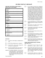
Table 2 shows the operation of both modes of fan control
previously discussed.
HOT GAS BYPASS (LOADMINDER) OPTION
General
The Hot Gas Bypass Option is available as a factory
installed option to prevent compressor cycling and water
temperature fluctuation at low load. This is accomplished
by providing further capacity reduction below the last step
of compressor cylinder unloading by introducing an arti-
ficial load to the cooler, which keeps the compressor on
the line. The option will provide hot gas bypass on both
compressors enabling hot gas to be active regardless of
which compressor is in the lead.
TABLE 2 – LOW AMBIENT FAN CYCLING
NOTE:
Fans with reversing contactors will have the reversing contactors mechanically and electronically locked out when the fans are
running forward. The forward contactor will also be locked out when the fans are running in reverse.
NOTE: The microprocessor will only activate the hot gas
on the lead compressor.
The hot gas bypass consists of a pilot operated regulat-
ing valve with an integral solenoid. The pilot operated
solenoid is controlled by the microprocessor according
to water temperature. The regulating valve which becomes
activated when the solenoid is energized, is controlled
by suction pressure to modulate the flow of gas in a
bypass connected from the compressor discharge to the
cooler inlet. The following text will explain how the hot
gas solenoid is activated by the microprocessor in both
return and in leaving water control.
LWT Control Hot Gas Operation
The hot gas solenoid is energized when the leaving wa-
ter temperature falls below the “Target” water tempera-
ture, if the compressor is on its minimum stage of load-
ing. Hot gas may then be fed according to the suction
pressure and the pressure regulating valve setting. Once
CONTROL BY
CONTROL BY
TEMPERATURE & PRESSURE
PRESSURE ONLY
SYS
FAN
CONTACTOR
BELOW 25°F (-3.9°C)
ABOVE 25°F (-3.9°C)
TEMPERATURE
PRESSURE CONTROL
TEMPERATURE CONTROL ONLY
HAS NO EFFECT
ON
OFF
ON
OFF
ON
OFF
1 & 3 REV
9M & 10M
320 PSIG
120 PSIG
Will Not Start
35°F (1.7°C) or
320 PSIG
120 PSIG
(2.2 mPa)
(827.4 kPa)
Above 25°F (-3.9°C) 340 PSIG (2.3 mPa)
(2.2 mPa)
(827.4 kPa)
Turns OFF by
1
2 & 4
6M & 8M
340 PSIG
120 PSIG
25°F
Pressure
340 PSIG
120 PSIG
(2.3 mPa)
(827.4 kPa)
(-3.9°C)
Only at 120 PSIG
(2.3 mPa)
(827.4 kPa)
(827.4 kPa)
1 & 3 FWD
5M & 7M
360 PSIG
140 PSIG
45°F
40°F
360 PSIG
140 PSIG
(2.5 mPa)
(965.3 kPa)
(7.2°C)
(4.4°C)
(2.5 mPa)
(965.3 kPa)
5 & 7 REV
15M & 16M
320 PSIG
120 PSIG
Will Not Start
35°F (1.7°C) or
320 PSIG
120 PSIG
(2.2 mPa)
(827.4 kPa)
Above 25°F (-3.9°C) 340 PSIG (2.3 mPa)
(2.2 mPa)
(827.4 kPa)
Turns OFF by
2
6 & 8
12M & 14M
340 PSIG
120 PSIG
25°F
Pressure
320 PSIG
120 PSIG
(2.3 mPa)
(827.4 kPa)
(-3.9°C)
Only at 120 PSIG
(2.2 mPa)
(827.4 kPa)
(827.4 kPa)
5 & 7 FWD
11M & 13M
360 PSIG
140 PSIG
45°F
40°F
340 PSIG
140 PSIG
(2.5 mPa)
(965.3 kPa)
(7.2°C)
(4.4°C)
(2.3 mPa)
(965.3 kPa)
Содержание Millennium YCAJ150
Страница 21: ...FORM 150 65 NM4 21 YORK INTERNATIONAL LD02461 FIG 6 ELEMENTARY DIAGRAM Cont d...
Страница 22: ...22 YORK INTERNATIONAL ELEMENTARY DIAGRAM...
Страница 24: ...24 YORK INTERNATIONAL CONNECTION DIAGRAM FIG 7 CONNECTION DIAGRAM LD02463...
Страница 25: ...FORM 150 65 NM4 25 YORK INTERNATIONAL FIG 7 CONNECTION DIAGRAM Cont d LD02462...
Страница 26: ...26 YORK INTERNATIONAL CONNECTION DIAGRAM TERMINAL BOX AND SYSTEM WIRING FIG 8 SYSTEM WIRING LD02464...
Страница 28: ...28 YORK INTERNATIONAL CONNECTION DIAGRAM TERMINAL BOX AND SYSTEM WIRING FIG 8 SYSTEM WIRING Cont d LD02650...
Страница 30: ...30 YORK INTERNATIONAL FIG 8 SYSTEM WIRING Cont d LD02499...
Страница 100: ...100 YORK INTERNATIONAL LD02654 FIG 37B LOUVER BRACKETS INSTALLATION...
Страница 101: ...FORM 150 65 NM4 101 YORK INTERNATIONAL LD02655 FIG 37C GRILLE AND LOUVER INSTALLATION FRONT AND BACK...
Страница 103: ...FORM 150 65 NM4 103 YORK INTERNATIONAL LD02656 FIG 39A LOUVER INSTALLATION SIDES...
Страница 104: ...104 YORK INTERNATIONAL LD02654 FIG 39B LOUVER BRACKETS INSTALLATION...
Страница 105: ...FORM 150 65 NM4 105 YORK INTERNATIONAL LD02657 FIG 39C GRILLE AND LOUVER INSTALLATION FRONT AND BACK...
Страница 107: ...FORM 150 65 NM4 107 YORK INTERNATIONAL FIG 40A CONDENSER COIL LOUVER INSTALLATION SIDES LD02658...
Страница 108: ...108 YORK INTERNATIONAL FIG 40B CONDENSER COIL LOUVER INSTALLATION FRONT AND BACK LD02659...
Страница 110: ...110 YORK INTERNATIONAL FIG 41 REMOTE RESET BOARD LD02666 P1...