


62
YORK INTERNATIONAL
The Discharge Pressure Safety Cut-out is programmable
by the user (Page 43). An example of a discharge pres-
sure fault display message is shown below.
NOTE: This safety is only operable if optional discharge
pressure transducers are installed.
Oil Pressure Safety
The Oil Pressure Safety assures that the compressor’s
mechanical components receive proper lubrication. The
micro begins monitoring compressor oil pressure after 4
seconds of operation. For operating periods of 4 sec-
onds to 30 seconds, oil pressure must be greater than 5
PSID (34.5 kPa). From 30 seconds to 240 seconds, oil
pressure must be greater than 20 PSID (137.9 kPa).
After 240 seconds, oil pressure must be greater than 25
PSID (172.4 kPa) for as long as the compressor contin-
ues to run. If the required oil pressure limits are not met,
the system will shut down.
The micro computes “differential oil pressure” by mea-
suring oil pump pressure and subtracting suction pres-
sure (Oil - Suction = Oil PSID).
An example of an oil pressure fault display message is
shown below.
Pumpdown Safety
The Pumpdown Safety assures that a compressor does
not run unless it completes a proper pumpdown. This
prevents operation of a refrigerant system which has a
leaking liquid line solenoid valve.
On shutdown, the system must pump down to the suc-
tion pressure cut-out within 300 seconds or the system
will shut down. If the system performs 3 unsuccessful
pumpdowns in a row, the system will fault and lockout.
An example of the Pumpdown Fault display message is
shown below.
High Oil Temp Safety
This safety protects the compressor from catastrophic
failure by sensing when an internal problem occurs that
S Y S # 1
H I G H
D S C H
S Y S # 2
H I G H
D S C H
S Y S # 1
L O W
O I L
P R E S S
S Y S # 2
L O W
O I L
P R E S S
S Y S # 1
P U M P D O W N
F A I L
S Y S # 2
P U M P D O W N
F A I L
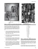
shut down. For more information see the MOTOR CUR-
RENT SAFETY section (Page 61).
Auto-restart will be permitted after a shutdown when dis-
charge pressure drops to below 330 PSIG (2.3 mPa)
which allows the mechanical high pressure cut-out to
reset and its contacts to close. This re-applies 115VAC
to the motor protector closing the MP contact. A fault
lock-out will result if safety thresholds are exceeded three
times in a 90-minute period.
Suction Pressure Safety
The Suction Pressure Safety assures that the system is
not run under low refrigerant conditions or due to a prob-
lem which will not allow proper refrigerant flow.
For the first 30 seconds of operation, the low suction
pressure bypass is in operation. After 30 seconds of
operation, the micro begins monitoring suction pressure
and continues to do so as long as the compressor runs.
For operation periods of 30 seconds to 240 seconds,
suction pressure must be greater than 50% of the Suc-
tion Pressure Cut-out. After 240 seconds, suction pres-
sure must be greater than the cut-out.
NOTE: A transient timer is built into software to assure
that short term fluctuations in suction pressure
due to fan cycling, loading, etc. do not cause
nuisance trips on low suction pressure.
After the system has pumped down and suction
pressure reaches cut-out plus 5 PSIG, the tran-
sient timer is readied for action. If suction pres-
sure drops below the cut-out point, the 120 sec-
ond transient timer begins timing. As long as
suction pressure doesn’t drop below 50% of cut-
out during the 120 second period and rises above
cut-out before the timer times out, the system
will continue to run.
The Suction Pressure Safety Cut-out is programmable
by the user (Page 46). An example of a suction pres-
sure fault message is shown below.
Discharge Pressure Safety
The Discharge Pressure Safety assures that the sys-
tem pressure does not exceed safe working limits which
could open a relief valve or other pressure relief device
causing refrigerant loss.
This safety is a back-up for the mechanical safety in the
system. Anytime the cut-out point is exceeded, the sys-
tem will shut down.
S Y S # 1
L O W
S U C T I O N
S Y S # 2
L O W
S U C T I O N
Содержание Millennium YCAJ150
Страница 21: ...FORM 150 65 NM4 21 YORK INTERNATIONAL LD02461 FIG 6 ELEMENTARY DIAGRAM Cont d...
Страница 22: ...22 YORK INTERNATIONAL ELEMENTARY DIAGRAM...
Страница 24: ...24 YORK INTERNATIONAL CONNECTION DIAGRAM FIG 7 CONNECTION DIAGRAM LD02463...
Страница 25: ...FORM 150 65 NM4 25 YORK INTERNATIONAL FIG 7 CONNECTION DIAGRAM Cont d LD02462...
Страница 26: ...26 YORK INTERNATIONAL CONNECTION DIAGRAM TERMINAL BOX AND SYSTEM WIRING FIG 8 SYSTEM WIRING LD02464...
Страница 28: ...28 YORK INTERNATIONAL CONNECTION DIAGRAM TERMINAL BOX AND SYSTEM WIRING FIG 8 SYSTEM WIRING Cont d LD02650...
Страница 30: ...30 YORK INTERNATIONAL FIG 8 SYSTEM WIRING Cont d LD02499...
Страница 100: ...100 YORK INTERNATIONAL LD02654 FIG 37B LOUVER BRACKETS INSTALLATION...
Страница 101: ...FORM 150 65 NM4 101 YORK INTERNATIONAL LD02655 FIG 37C GRILLE AND LOUVER INSTALLATION FRONT AND BACK...
Страница 103: ...FORM 150 65 NM4 103 YORK INTERNATIONAL LD02656 FIG 39A LOUVER INSTALLATION SIDES...
Страница 104: ...104 YORK INTERNATIONAL LD02654 FIG 39B LOUVER BRACKETS INSTALLATION...
Страница 105: ...FORM 150 65 NM4 105 YORK INTERNATIONAL LD02657 FIG 39C GRILLE AND LOUVER INSTALLATION FRONT AND BACK...
Страница 107: ...FORM 150 65 NM4 107 YORK INTERNATIONAL FIG 40A CONDENSER COIL LOUVER INSTALLATION SIDES LD02658...
Страница 108: ...108 YORK INTERNATIONAL FIG 40B CONDENSER COIL LOUVER INSTALLATION FRONT AND BACK LD02659...
Страница 110: ...110 YORK INTERNATIONAL FIG 41 REMOTE RESET BOARD LD02666 P1...