


38
YORK INTERNATIONAL
SWITCH 8
OPEN:
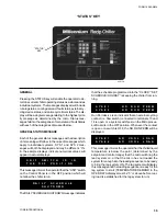
Fan control will be by outside ambient temp. This will be
the standard mode of fan control for normal operation. In
this mode, maximum chiller efficiency will be achieved. If
the Low Ambient option is installed, the fan control will
automatically change to pressure control at temperatures
below 25°F (-3.9°C). See page 79 for fan control sequence.
CLOSED:
Fan control is by discharge pressure only. This mode of
fan control will increase discharge pressure. It should be
used if nuisance low suction pressure faults are experi-
enced. See page 93 for fan control sequence.
NOTE: Discharge pressure transducers must be in-
stalled. These are optional (Discharge Pressure
Read-out Option) unless a Low Ambient Kit is
installed.
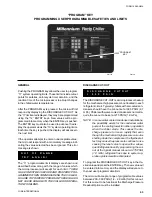
SWITCH 7
OPEN:
SYS 1 can be selected as the lag compressor by clos-
ing a user supplied contact between Terminals 13 and
19. See Page 74.
CLOSED:
In this mode, the micro determines which compressor is
assigned to the lead and the lag. A new lead/lag assign-
ment is made whenever both compressors shut down.
The micro will then assign the “lead” to the compressor
with the shortest anti-recycle time.
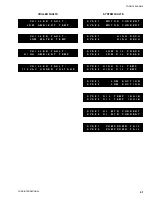
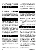
M A N U A L
L E A D
/
L A G
A M B I E N T
&
D I S C H
P R
F A N
C O N T R O L
A U T O M A T I C
L E A D
/
L A G
D I S C H A R G E
P R E S S U R E
F A N
C O N T R O L
Содержание Millennium YCAJ150
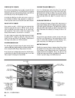
Страница 21: ...FORM 150 65 NM4 21 YORK INTERNATIONAL LD02461 FIG 6 ELEMENTARY DIAGRAM Cont d...
Страница 22: ...22 YORK INTERNATIONAL ELEMENTARY DIAGRAM...
Страница 24: ...24 YORK INTERNATIONAL CONNECTION DIAGRAM FIG 7 CONNECTION DIAGRAM LD02463...
Страница 25: ...FORM 150 65 NM4 25 YORK INTERNATIONAL FIG 7 CONNECTION DIAGRAM Cont d LD02462...
Страница 26: ...26 YORK INTERNATIONAL CONNECTION DIAGRAM TERMINAL BOX AND SYSTEM WIRING FIG 8 SYSTEM WIRING LD02464...
Страница 28: ...28 YORK INTERNATIONAL CONNECTION DIAGRAM TERMINAL BOX AND SYSTEM WIRING FIG 8 SYSTEM WIRING Cont d LD02650...
Страница 30: ...30 YORK INTERNATIONAL FIG 8 SYSTEM WIRING Cont d LD02499...
Страница 100: ...100 YORK INTERNATIONAL LD02654 FIG 37B LOUVER BRACKETS INSTALLATION...
Страница 101: ...FORM 150 65 NM4 101 YORK INTERNATIONAL LD02655 FIG 37C GRILLE AND LOUVER INSTALLATION FRONT AND BACK...
Страница 103: ...FORM 150 65 NM4 103 YORK INTERNATIONAL LD02656 FIG 39A LOUVER INSTALLATION SIDES...
Страница 104: ...104 YORK INTERNATIONAL LD02654 FIG 39B LOUVER BRACKETS INSTALLATION...
Страница 105: ...FORM 150 65 NM4 105 YORK INTERNATIONAL LD02657 FIG 39C GRILLE AND LOUVER INSTALLATION FRONT AND BACK...
Страница 107: ...FORM 150 65 NM4 107 YORK INTERNATIONAL FIG 40A CONDENSER COIL LOUVER INSTALLATION SIDES LD02658...
Страница 108: ...108 YORK INTERNATIONAL FIG 40B CONDENSER COIL LOUVER INSTALLATION FRONT AND BACK LD02659...
Страница 110: ...110 YORK INTERNATIONAL FIG 41 REMOTE RESET BOARD LD02666 P1...