


82
YORK INTERNATIONAL
hours before start-up. This is important to as-
sure no refrigerant is in the oil at start-up!
'
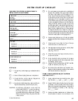
4. Program the Dip Switches on the Micropro-
cessor Board (Page 36 - 38) and verify the se-
lection by pressing the OPTIONS key.
Switch 3 should always be closed.
Switch 6 should always be open.
NOTE: It is IMPORTANT that all switches are properly
programmed. Otherwise, undesirable operation
will result.
'
5. Press the PROGRAM key and program each
of the 11 limits and record them. They are as
follows*:
'
• Discharge Cutout
____ PSIG
'
• Outside Air Temp Low Cutout
____ °F
'
• Outside Air Temp High Cutout
____ °F
'
• Discharge Pressure Unload Pressure____ PSIG
'
• Suction Pressure Unload Pressure
____ PSIG
'
• Leaving Water Temp Cutout
____ °F
'
• Suction Pressure Cutout
____ PSIG
'
• Rate Control Temp
____ °F
'
• Anti Recycle Time
____ SEC
'
• Rate Sensitivity
____ °F/MlN
'
• Number of Load Steps
____
* substitute metric value if required
See page 43 for assistance in programming
these values.
'
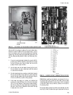
6. Program the date and time by first assuring
that the CLK jumper J18 on the Microproces-
sor Board (Fig. 26) is in the ON position (Top 2
pins).
Press the SET TIME key and set the date and
time (Page 47).
'
7. Program the Daily and Holiday Start/Stop
Schedule by pressing the SET SCHEDULE/
HOLIDAY key (Page 47).
'
8. Program the Chilled Liquid Setpoint and Con-
trol Range by pressing the CHILLED LIQUID
TEMP/RANGE key (Page 51).
'
9. If the Remote Reset is to be used, the maxi-
mum reset must be programmed. This can be
programmed by pressing the REMOTE RESET
TEMP RANGE key (Page 77).
INITIAL STARTUP
After the operator has become thoroughly familiar with
the control panel and has performed the preceeding
checks 24 hours prior to startup, the unit can be put into
operation.
'
Place the System Switches to the ON position.
See the OPERATING SEQUENCE for unit opera-
tion.
'
The compressor will start and a flow of liquid should
be noted in the liquid indicator. After several min-
utes of operation, the bubbles will disappear and
there will be a solid column of liquid when the unit
is operating normally. On startup, foaming of the
oil may be evident in the compressor oil sight
glass. After the water temperature has been pulled
down to operating conditions, the oil should be
clear. Normal operation of the unit is evidenced
by a hot discharge line (discharge superheat
should not drop below 50°F or 10°C), clear oil in
the compressor crankcase, solid liquid refriger-
ant in the liquid indicator and usually no more
than 2 PSIG (13.8 kPa) variation in suction pres-
sure for any given set of operating conditions.
'
Allow the compressor to run for a short time, be-
ing ready to stop it immediately if any unusual
noise or other adverse condition should develop.
When starting the compressor, always make sure
the oil pump is functioning properly. Compressor
oil pressure must be as described in the SYS-
TEM SAFETIES Section, page 62.
'
Check the system operating parameters. Do this
by selecting various readouts such as pressures
and temperatures. Compare these to test gauge
readings.
CHECKING SUPERHEAT AND SUBCOOLING
The subcooling should always be checked when charg-
ing the system with refrigerant and/or before setting the
superheat.
When the refrigerant charge is correct, there will be no
bubbles in the liquid sightglass with the system operat-
ing under full load conditions, and there will be 10°F to
15°F (-12.2 to -9.4°C) subcooled liquid refrigerant leaving
the condenser.
An overcharged system should be guarded against. Evi-
dences of overcharge are as follows:
a.
If a system is overcharged, the discharge pressure
will be higher than normal. (Normal discharge/con-
densing pressure can be found in refrigerant tem-
perature/pressure chart; use entering air tempera-
ture +30°F {-1.1°C] for normal condensing tempera-
tures.)
b.
The temperature of the liquid refrigerant out of the
condenser should not be more than 15°F (8.3°C)
less than the condensing temperature. (The tem-
perature corresponding to the condensing pressure
from refrigerant temperature/pressure chart).
Содержание Millennium YCAJ150
Страница 21: ...FORM 150 65 NM4 21 YORK INTERNATIONAL LD02461 FIG 6 ELEMENTARY DIAGRAM Cont d...
Страница 22: ...22 YORK INTERNATIONAL ELEMENTARY DIAGRAM...
Страница 24: ...24 YORK INTERNATIONAL CONNECTION DIAGRAM FIG 7 CONNECTION DIAGRAM LD02463...
Страница 25: ...FORM 150 65 NM4 25 YORK INTERNATIONAL FIG 7 CONNECTION DIAGRAM Cont d LD02462...
Страница 26: ...26 YORK INTERNATIONAL CONNECTION DIAGRAM TERMINAL BOX AND SYSTEM WIRING FIG 8 SYSTEM WIRING LD02464...
Страница 28: ...28 YORK INTERNATIONAL CONNECTION DIAGRAM TERMINAL BOX AND SYSTEM WIRING FIG 8 SYSTEM WIRING Cont d LD02650...
Страница 30: ...30 YORK INTERNATIONAL FIG 8 SYSTEM WIRING Cont d LD02499...
Страница 100: ...100 YORK INTERNATIONAL LD02654 FIG 37B LOUVER BRACKETS INSTALLATION...
Страница 101: ...FORM 150 65 NM4 101 YORK INTERNATIONAL LD02655 FIG 37C GRILLE AND LOUVER INSTALLATION FRONT AND BACK...
Страница 103: ...FORM 150 65 NM4 103 YORK INTERNATIONAL LD02656 FIG 39A LOUVER INSTALLATION SIDES...
Страница 104: ...104 YORK INTERNATIONAL LD02654 FIG 39B LOUVER BRACKETS INSTALLATION...
Страница 105: ...FORM 150 65 NM4 105 YORK INTERNATIONAL LD02657 FIG 39C GRILLE AND LOUVER INSTALLATION FRONT AND BACK...
Страница 107: ...FORM 150 65 NM4 107 YORK INTERNATIONAL FIG 40A CONDENSER COIL LOUVER INSTALLATION SIDES LD02658...
Страница 108: ...108 YORK INTERNATIONAL FIG 40B CONDENSER COIL LOUVER INSTALLATION FRONT AND BACK LD02659...
Страница 110: ...110 YORK INTERNATIONAL FIG 41 REMOTE RESET BOARD LD02666 P1...