


78
YORK INTERNATIONAL
Once the maximum reset is programmed, it will require
a contact closure of 21 seconds to achieve the maxi-
mum reset. Closure for less than 21 seconds will provide
a smaller reset. For noise immunity, the micro will ig-
nore closures of less than 1 second.
To compute the offset for a given timer closed, use the
formula below:
1.
Programmed max. reset
20 seconds
=
Reset per sec.
2. (Time Closed - 1) Reset per sec. = Reset
Example:
Programmed max reset = 30°; Time Closed = 9 sec.
1.
30°
=
1.5° per sec.
20 sec.
2. (9 sec. -1 sec.) 1.5° per sec. = 12° = Reset
To determine the new setpoints, add the reset to the
setpoint programmed into memory. In the example above,
if the programmed setpoint = 44°F, the new setpoint af-
ter the 9 second contact closure would be 44°F + 12°F
= 56°F. This new setpoint can be viewed on the display
by pressing the REMOTE RESET TEMP/RANGE key.
To maintain a given offset, the micro must be refreshed
every 30 seconds - 30 minutes with a contact closure of
the required time period. It will not accept a refresh sooner
than 30 seconds after the end of the last PWM signal,
but must be refreshed before a period of 30 minutes ex-
pires from the end of the last PWM signal.
After 30 minutes, if no refresh is provided, the setpoint
will change back to its original value. A refresh is nothing
more than a contact closure for the period required for
the desired offset.
NOTE: After an offset signal, the new setpoint may be
viewed on the REMOTE RESET TEMP RANGE
DISPLAY However, if this display is being viewed
when the reset pulse occurs, the setpoint will
not change on the display. To view the new off-
set, first press any other display key on the key-
pad and then press the REMOTE RESET TEMP
RANGE key. The new setpoint will then appear.
Wiring from these contacts should not exceed 25 ft. and
should be run in grounded conduit that does not carry
any wiring other than control wiring. Additionally, if an
inductive device (relay, contactor) is supplying these con-
tacts, the coil of the device must be suppressed with a
user supplied YORK P/N 031-00808 suppressor.
NOTE: Remote Setpoint Reset will not operate when a
Remote Control Center Option Kit is connected
to the Micro Panel, The Remote Control Center
will always determine the setpoint.
REMOTE UNLOADING
The microprocessor is capable of remote unloading or
pulldown demand limiting in two steps. The first step
shuts down the lag system. The second step unloads
the lead system to its minimum step of capacity which
places the entire system at minimum possible capacity.
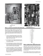
To shut down the lag compressor, a “dry” contact should
be connected between terminals 13 & 16. See Fig. 12
for the location of these terminals. When the contact is
closed, the lag compressor will shut down.
Before the lead system can be unloaded to its minimum
step of capacity, the lag compressor must already be
disabled with a “dry” contact closure between terminal
13 & 16 as described in the preceding paragraph.
With contacts on Terminals 13 & 16 closed, the lead
system can be unloaded to its minimum step of capac-
ity by closing a “dry” contact connected between termi-
nals 13 & 17. See Fig. 12 for location of this terminal.
The lead system will remain totally unloaded as long as
the contacts remain closed on both 13 & 16 and 13 &
17. It should be noted that terminals 13 & 17 are nor-
mally used for Remote Setpoint Reset. However, it is
assumed that if the lag system is purposely being shut
down, Remote Setpoint Reset and temperature control
is of no importance. This is generally true since capacity
control of the load is lost when a large portion of the
capacity is disabled.
CAUTION: Two cautions should be observed when us-
ing these functions. Observing these cau-
tions will assure that undesirable operation
does not result.
1.
Terminals 13 & 17 contact should always
be closed after or simultaneous with those
on 13 & 16, when unloading of the lead sys-
tem is desired. Otherwise, the microproces-
sor may mistake the closed contacts on 13
& 17 as a signal for a setpoint reset.
2.
Terminal 13 & 17 contact should always be
opened before or simultaneous with those
on 13 & 16 when loading is desired. Other-
wise, the microprocessor may mistake the
closed contacts on 13 & 17 as a signal for
a setpoint reset.
Содержание Millennium YCAJ150
Страница 21: ...FORM 150 65 NM4 21 YORK INTERNATIONAL LD02461 FIG 6 ELEMENTARY DIAGRAM Cont d...
Страница 22: ...22 YORK INTERNATIONAL ELEMENTARY DIAGRAM...
Страница 24: ...24 YORK INTERNATIONAL CONNECTION DIAGRAM FIG 7 CONNECTION DIAGRAM LD02463...
Страница 25: ...FORM 150 65 NM4 25 YORK INTERNATIONAL FIG 7 CONNECTION DIAGRAM Cont d LD02462...
Страница 26: ...26 YORK INTERNATIONAL CONNECTION DIAGRAM TERMINAL BOX AND SYSTEM WIRING FIG 8 SYSTEM WIRING LD02464...
Страница 28: ...28 YORK INTERNATIONAL CONNECTION DIAGRAM TERMINAL BOX AND SYSTEM WIRING FIG 8 SYSTEM WIRING Cont d LD02650...
Страница 30: ...30 YORK INTERNATIONAL FIG 8 SYSTEM WIRING Cont d LD02499...
Страница 100: ...100 YORK INTERNATIONAL LD02654 FIG 37B LOUVER BRACKETS INSTALLATION...
Страница 101: ...FORM 150 65 NM4 101 YORK INTERNATIONAL LD02655 FIG 37C GRILLE AND LOUVER INSTALLATION FRONT AND BACK...
Страница 103: ...FORM 150 65 NM4 103 YORK INTERNATIONAL LD02656 FIG 39A LOUVER INSTALLATION SIDES...
Страница 104: ...104 YORK INTERNATIONAL LD02654 FIG 39B LOUVER BRACKETS INSTALLATION...
Страница 105: ...FORM 150 65 NM4 105 YORK INTERNATIONAL LD02657 FIG 39C GRILLE AND LOUVER INSTALLATION FRONT AND BACK...
Страница 107: ...FORM 150 65 NM4 107 YORK INTERNATIONAL FIG 40A CONDENSER COIL LOUVER INSTALLATION SIDES LD02658...
Страница 108: ...108 YORK INTERNATIONAL FIG 40B CONDENSER COIL LOUVER INSTALLATION FRONT AND BACK LD02659...
Страница 110: ...110 YORK INTERNATIONAL FIG 41 REMOTE RESET BOARD LD02666 P1...