


FORM 150.65-NM4
69
YORK INTERNATIONAL
LOCAL DISPLAY READOUT
Oper Data
The OPER DATA key also allows the user to scroll through
additional real time display information about the chiller
system which is not available from the DISPLAY keys.
This information covers a wide range of data which in-
cludes fan status, loading status, liquid line solenoid
status, run time, etc. A total of 20 different displays are
offered.
When the OPER DATA key is pressed, the following
message will appear:
Repetitively pressing the ENTER key allows the opera-
tor to scroll through the 20 available displays.
In the information that follows, a sample message along
with an explanation of its meaning is provided for all 20
messages.
This message provides a real time display of the time
left on the Load Timer. The Load Timer is a constantly
recycling timer that the micro utilizes in conjunction with
“rate control” and “temperature deviation from setpoint”
to determine when loading should occur. The timer will
always start at 150 sec.; however, it may count to “0” at
a rate of up to 5 secs. per actual second of time.
This message provides a real timer display of the time
left on the Unload Timer. The Unload Timer is a con-
stantly recycling timer that the micro utilizes in conjunc-
tion with “rate control” and “temperature deviation from
setpoint” to determine when unloading should occur. The
timer will always start at 150 sec.; however, it may count
to “0” at a rate of up to 5 secs. per actual second of time.
This message informs the operator what stage of load-
ing the chiller system is presently on as a result of com-
mands from the microprocessor. This is a coded number
and the steps must be decoded to be meaningful. The
decoding varies according to the number of stages pro-
grammed (Page 46). Tables for decoding the display
message are shown at the top of the next column:
P R E S S
E N T E R
T O
D I S P L A Y
D A T A
L O A D
T I M E R
1 4 0
S E C S
U N L O A D
T I M E R
1 2 2
S E C S
T E M P E R A T U R E
D E M A N D
5 STAGE
STEP
0:
Both Compressors OFF
*1:
Lead Compr Unloaded, Lag Compr OFF
*2:
Lead Compr Unloaded, Lag Compr OFF
*3:
Lead Compr Loaded, Lag Compr OFF
*4:
Lead Compr Loaded, Lag Compr OFF
*5:
Lead Compr Unloaded, Lag Compr Unloaded
*6:
Lead Compr Unloaded, Lag Compr Unloaded
*7:
Lead Compr Loaded, Lag Compr Unloaded
*8:
Lead Compr Loaded, Lag Compr Unloaded
*9:
Lead Compr Loaded, Lag Compr Loaded
*10:
Lead Compr Loaded, Lag Compr Loaded
* On some “STEPS”, actual Loading will NOT change.
7 STAGE
STEP
0:
Both Compressors OFF
1:
Lead Compr Unloaded, Lag Compr OFF
*2:
Lead Compr 1 Stage Loading, Lag Compr OFF
*3:
Lead Compr 1 Stage Loading, Lag Compr OFF
4:
Lead Compr 2 Stages Loading, Lag Compr OFF
5:
Lead Compr 1 Stage Loading,
Lag Compr Unloaded
*6:
Lead Compr 1 Stage Loading,
Lag Compr 1 Stage Loading
*7:
Lead Compr 1 Stage Loading,
Lag Compr 1 Stage Loading
*8:
Lead Compr 1 Stage Loading,
Lag Compr 1 Stage Loading
9:
Lead Compr 2 Stages Loading,
Lag Compr 1 Stage Loading
10:
Lead Compr 2 Stages Loading,
Lag Compr 2 Stages Loading
10 STAGE
STEP
0:
Both Compressors OFF
1:
Lead Compr Unloaded, Lag Compr OFF
2:
Lead Compr 1 Stage Loading, Lag Compr OFF
3:
Lead Compr 2 Stages Loading, Lag Compr OFF
4:
Lead Compr 3 Stages Loading, Lag Compr OFF
5:
Lead Compr 2 Stages Loading,
Lag Compr Unloaded
6:
Lead Compr 1 Stage Loading,
Lag Compr 1 Stage Loading
Содержание Millennium YCAJ150
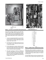
Страница 21: ...FORM 150 65 NM4 21 YORK INTERNATIONAL LD02461 FIG 6 ELEMENTARY DIAGRAM Cont d...
Страница 22: ...22 YORK INTERNATIONAL ELEMENTARY DIAGRAM...
Страница 24: ...24 YORK INTERNATIONAL CONNECTION DIAGRAM FIG 7 CONNECTION DIAGRAM LD02463...
Страница 25: ...FORM 150 65 NM4 25 YORK INTERNATIONAL FIG 7 CONNECTION DIAGRAM Cont d LD02462...
Страница 26: ...26 YORK INTERNATIONAL CONNECTION DIAGRAM TERMINAL BOX AND SYSTEM WIRING FIG 8 SYSTEM WIRING LD02464...
Страница 28: ...28 YORK INTERNATIONAL CONNECTION DIAGRAM TERMINAL BOX AND SYSTEM WIRING FIG 8 SYSTEM WIRING Cont d LD02650...
Страница 30: ...30 YORK INTERNATIONAL FIG 8 SYSTEM WIRING Cont d LD02499...
Страница 100: ...100 YORK INTERNATIONAL LD02654 FIG 37B LOUVER BRACKETS INSTALLATION...
Страница 101: ...FORM 150 65 NM4 101 YORK INTERNATIONAL LD02655 FIG 37C GRILLE AND LOUVER INSTALLATION FRONT AND BACK...
Страница 103: ...FORM 150 65 NM4 103 YORK INTERNATIONAL LD02656 FIG 39A LOUVER INSTALLATION SIDES...
Страница 104: ...104 YORK INTERNATIONAL LD02654 FIG 39B LOUVER BRACKETS INSTALLATION...
Страница 105: ...FORM 150 65 NM4 105 YORK INTERNATIONAL LD02657 FIG 39C GRILLE AND LOUVER INSTALLATION FRONT AND BACK...
Страница 107: ...FORM 150 65 NM4 107 YORK INTERNATIONAL FIG 40A CONDENSER COIL LOUVER INSTALLATION SIDES LD02658...
Страница 108: ...108 YORK INTERNATIONAL FIG 40B CONDENSER COIL LOUVER INSTALLATION FRONT AND BACK LD02659...
Страница 110: ...110 YORK INTERNATIONAL FIG 41 REMOTE RESET BOARD LD02666 P1...