


FORM 150.65-NM4
51
YORK INTERNATIONAL
GENERAL
After Return or Leaving Chilled Liquid Control is selected
according to the user’s application and Switch #4 of Dip
Switch S1 on the Micro Board is properly configured to
select Return or Leaving control, the chilled liquid set-
points can then be programmed into the control panel.
Switch #4 of S1 must be properly programmed or an
incorrect display message will appear when the CHILLED
LIQUID TEMP/RANGE key is pressed.
SEE “SELEC-
TION OF RETURN OR LEAVING CHILLED LIQUID
CONTROL” Page 50 if needed.
If remote temperature setpoint is being utilized, the RE-
MOTE RESET TEMP RANGE must be programmed.
The following information will cover programming both
return and leaving control. Refer to either the RETURN
or LEAVING WATER CONTROL section as required be-
low. Programming the REMOTE RESET TEMP RANGE
is discussed later in this manual on Page 77.
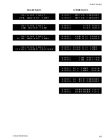
PROGRAMMING RETURN WATER CONTROL
Chilled Liquid
Temp/Range
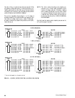
When the CHILLED LIQUID TEMP/RANGE key is
pressed, the following message will be displayed for 3
seconds indicating Dip Switch S1, Switch #4 on the Mi-
croprocessor Board is programmed properly:
If this message is incorrect, see the “SELECTION OF
RETURN OR LEAVING CHILLED LIQUID CONTROL”
section (Page 50) for instructions to reprogram the Mi-
croprocessor Dip Switch S1, Switch #4.
The display will then scroll to a second message & hold:
This message will display the user’s “Design Leaving
Water Temperature” (LWT) setpoint (44.0° F [6.7°C] in
the sample above). Even though return water tempera-
ture control is being utilized, the object is to provide con-
stant design leaving water temperature. It is the “Design
Leaving Water Temperature” setpoint (LWT) which must
be programmed into the microprocessor.
Also included in this message is the “CONTROL RANGE”
(CR). The “CONTROL RANGE” is the temperature range
which loading/unloading will take place. The lower limit
of the CONTROL RANGE is always equal to the setpoint
and automatically appears when the setpoint is keyed
in. The upper limit of the CR must be programmed.
In the above sample message, with a “CR = 44.0 - 54.0°F
(6.7 - 12.2°C)”, the chiller will be completely off at a re-
turn water temperature of 44.0°F (6.7°C) and fully loaded
at a return water temperature of 54.0°F (12.2°C). Partial
loading will occur in equal temperature intervals between
44° and 54°F (6.7 and 12.2°C). Unloading will occur as
return temperature drops below 54°F (12.2°C) with the
chiller cycling completely off at 44.0°F (6.7°C). These
Photo #
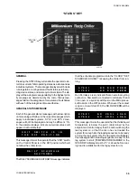
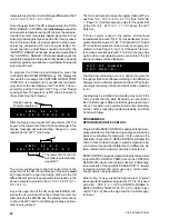
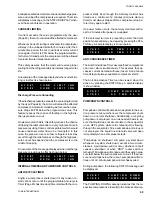
“SETPOINTS” KEYS
PROGRAMMING CHILLED LIQUID SETPOINTS AND REMOTE RESET TEMP RANGE
“SETPOINTS”
KEYS
CHILLED LIQUID
TEMP / RANGE
R E T U R N
W A T E R
T E M P
C O N T R O L
L W T =
4 4 . 0
F
C R =
4 4 . 0
T O
5 4 . 0
F
02711TG
Содержание Millennium YCAJ150
Страница 21: ...FORM 150 65 NM4 21 YORK INTERNATIONAL LD02461 FIG 6 ELEMENTARY DIAGRAM Cont d...
Страница 22: ...22 YORK INTERNATIONAL ELEMENTARY DIAGRAM...
Страница 24: ...24 YORK INTERNATIONAL CONNECTION DIAGRAM FIG 7 CONNECTION DIAGRAM LD02463...
Страница 25: ...FORM 150 65 NM4 25 YORK INTERNATIONAL FIG 7 CONNECTION DIAGRAM Cont d LD02462...
Страница 26: ...26 YORK INTERNATIONAL CONNECTION DIAGRAM TERMINAL BOX AND SYSTEM WIRING FIG 8 SYSTEM WIRING LD02464...
Страница 28: ...28 YORK INTERNATIONAL CONNECTION DIAGRAM TERMINAL BOX AND SYSTEM WIRING FIG 8 SYSTEM WIRING Cont d LD02650...
Страница 30: ...30 YORK INTERNATIONAL FIG 8 SYSTEM WIRING Cont d LD02499...
Страница 100: ...100 YORK INTERNATIONAL LD02654 FIG 37B LOUVER BRACKETS INSTALLATION...
Страница 101: ...FORM 150 65 NM4 101 YORK INTERNATIONAL LD02655 FIG 37C GRILLE AND LOUVER INSTALLATION FRONT AND BACK...
Страница 103: ...FORM 150 65 NM4 103 YORK INTERNATIONAL LD02656 FIG 39A LOUVER INSTALLATION SIDES...
Страница 104: ...104 YORK INTERNATIONAL LD02654 FIG 39B LOUVER BRACKETS INSTALLATION...
Страница 105: ...FORM 150 65 NM4 105 YORK INTERNATIONAL LD02657 FIG 39C GRILLE AND LOUVER INSTALLATION FRONT AND BACK...
Страница 107: ...FORM 150 65 NM4 107 YORK INTERNATIONAL FIG 40A CONDENSER COIL LOUVER INSTALLATION SIDES LD02658...
Страница 108: ...108 YORK INTERNATIONAL FIG 40B CONDENSER COIL LOUVER INSTALLATION FRONT AND BACK LD02659...
Страница 110: ...110 YORK INTERNATIONAL FIG 41 REMOTE RESET BOARD LD02666 P1...