


50
YORK INTERNATIONAL
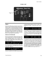
the micro panel must be interrogated to determine whether
it is programmed for RETURN or LEAVING WATER CON-
TROL. This can be accomplished by pressing the OP-
TION key in the DISPLAY section of the keypad. This
allows the user to determine the present mode of control
without gaining access to the Microprocessor Board and
visually checking the sometimes difficult to determine
Dip Switch position. When the OPTION key is pressed,
a message “THE FOLLOWING ARE PROGRAMMED”
will appear on the display for 3 seconds. The display will
then scroll through the 8 dip switch selections, each
appearing for 3 seconds. The 4th display will tell the
user whether leaving or return temperature is programmed
on Switch 4. The 4th display message will read either
“RETURN WATER CONTROL” or “LEAVING WATER
CONTROL“ and will appear for 3 seconds.
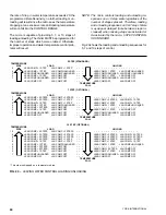
If a change is required, position Switch #4 on dip switch
S1 on the Microprocessor Board (Fig. 13) as indicated:
RWT CONTROL: SW 4 OPEN
(left side pushed down)
LWT CONTROL: SW 4 CLOSED
(right side pushed down)
NOTE: In LWT CONTROL, water temperature may un-
desirably rise when a compressor cycles off and
cannot restart because the anti-recycle timer is
still timing out. The effects can be reduced by
programming the anti-recycle timer (Page 45)
for a minimum of 300 seconds if it isn’t already
programmed for 300 seconds. If problems still
arise, switch to RWT CONTROL.
Once the dip switch #4 on the Microprocessor Board is
properly positioned, the user will be able to view the ap-
propriate display when the CHILLED LIQUID TEMP/
RANGE is pressed. This display will show one of the
following messages depending upon S1 positioning:
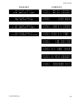
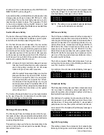
SELECTION OF RETURN OR LEAVING CHILLED LIQUID
R E T U R N
W A T E R
T E M P
C O N T R O L
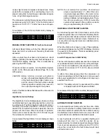
L E A V I N G
W A T E R
T E M P
C O N T R O L
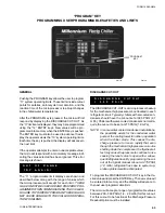
GENERAL
The user has the ability to select the type of chilled liq-
uid temperature control by choosing either Return or
Leaving Temperature Control. This provides the ability to
fine tune the method of control for comfort cooling or
batch/process cooling loads.
In many cases, comfort cooling will be best controlled
by RETURN WATER CONTROL. This will assure a mini-
mum of cycling compressors/loaders with stable leaving
chilled liquid temperatures as long as water flow GPM is
held constant and the Control Range (CR) is correctly
programmed.
LEAVING WATER CONTROL is also suitable for com-
fort cooling, but may produce slightly more cycling de-
pending upon the RATE SENSITIVITY programmed.
Optional stages of loading are recommended to reduce
cycling. In most cases, Leaving Water Control will be
more precise unless compressor cycling is encountered.
“Anticipation” and timers are built into the micro-
processor’s control algorithms to eliminate compressor
and loader cycling enabling LEAVING WATER CONTROL
to be used in most applications. The control algorithm
utilizes “PID” control.
For batch and process applications, LEAVING WATER
CONTROL will allow for precise temperature control. In
these applications chilled liquid temperature control is
more important than compressor/loader cycling. When
LEAVING WATER CONTROL is utilized, it is recom-
mended to have optional steps of loading on each com-
pressor. This assures minimum tonnage per step which
reduces the possibility of compressor and loader cycling
that is critical to precisely controlling temperature.
RETURN WATER CONTROL may also be used on batch
and process application and should provide adequate
control. However, it will prove to be less responsive with
slightly more leaving chilled liquid temperature variation.
RETURN WATER CONTROL may become necessary
to use if too much compressor cycling is noted with cor-
responding water temperature fluctuation when in Leav-
ing Water Control.
After determining the mode of control best suited for the
application (RETURN OR LEAVING WATER CONTROL),
Содержание Millennium YCAJ150
Страница 21: ...FORM 150 65 NM4 21 YORK INTERNATIONAL LD02461 FIG 6 ELEMENTARY DIAGRAM Cont d...
Страница 22: ...22 YORK INTERNATIONAL ELEMENTARY DIAGRAM...
Страница 24: ...24 YORK INTERNATIONAL CONNECTION DIAGRAM FIG 7 CONNECTION DIAGRAM LD02463...
Страница 25: ...FORM 150 65 NM4 25 YORK INTERNATIONAL FIG 7 CONNECTION DIAGRAM Cont d LD02462...
Страница 26: ...26 YORK INTERNATIONAL CONNECTION DIAGRAM TERMINAL BOX AND SYSTEM WIRING FIG 8 SYSTEM WIRING LD02464...
Страница 28: ...28 YORK INTERNATIONAL CONNECTION DIAGRAM TERMINAL BOX AND SYSTEM WIRING FIG 8 SYSTEM WIRING Cont d LD02650...
Страница 30: ...30 YORK INTERNATIONAL FIG 8 SYSTEM WIRING Cont d LD02499...
Страница 100: ...100 YORK INTERNATIONAL LD02654 FIG 37B LOUVER BRACKETS INSTALLATION...
Страница 101: ...FORM 150 65 NM4 101 YORK INTERNATIONAL LD02655 FIG 37C GRILLE AND LOUVER INSTALLATION FRONT AND BACK...
Страница 103: ...FORM 150 65 NM4 103 YORK INTERNATIONAL LD02656 FIG 39A LOUVER INSTALLATION SIDES...
Страница 104: ...104 YORK INTERNATIONAL LD02654 FIG 39B LOUVER BRACKETS INSTALLATION...
Страница 105: ...FORM 150 65 NM4 105 YORK INTERNATIONAL LD02657 FIG 39C GRILLE AND LOUVER INSTALLATION FRONT AND BACK...
Страница 107: ...FORM 150 65 NM4 107 YORK INTERNATIONAL FIG 40A CONDENSER COIL LOUVER INSTALLATION SIDES LD02658...
Страница 108: ...108 YORK INTERNATIONAL FIG 40B CONDENSER COIL LOUVER INSTALLATION FRONT AND BACK LD02659...
Страница 110: ...110 YORK INTERNATIONAL FIG 41 REMOTE RESET BOARD LD02666 P1...