


FORM 150.65-NM4
71
YORK INTERNATIONAL
This message informs the operator whether the Hot Gas
Solenoid is ON or OFF. The Micro will activate the Hot
Gas signal regardless of whether or not this option is
installed.
The Run Time for SYS 2 since the last start is displayed.
History
The HISTORY key also allows the user to scroll through
the SAFETY SHUTDOWN buffers to display information
relating to the last 3 Safety Shutdowns which occurred.
Information contained in the SAFETY SHUTDOWN Buff-
ers is very important when attempting to troubleshoot a
system problem. This data reflects system conditions
at the instant the fault occurred.
Information is stored in the SAFETY SHUTDOWN Buff-
ers on every fault regardless of whether the fault caused
a Lockout to occur. The information is also not affected
by power failures (long term internal memory battery
backup is built into the circuit board) or manual resetting
of a fault lockout.
When the HISTORY key is passed, the following mes-
sage will appear.
The operator must then select which SAFETY SHUT-
DOWN Buffer which is desired. When deciding this, keep
in mind that Buffer No. 1 is always the most recent fault.
As new fault information is stored, it is always placed in
Buffer No. 1, No. 1 is loaded to No. 2, No. 2 is loaded to
No. 3, and information previously in No. 3 is discarded.
To select a buffer, simply press the “1”, “2”, or “3” EN-
TRY key and press ENTER. Repetitively pressing the
ENTER key will allow the operator to scroll through the
information available in the SAFETY SHUTDOWN Buffer.
In the information that follows, a sample message along
with an explanation is provided for all available messages.
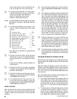
This message informs the operator of the time and date
of the fault.
S Y S
2
H O T
G A S
B Y P A S S
V A L V E
S T A T U S
O N
S Y S
2
R U N
T I M E
0
S E C S
D I S P L A Y
S A F E T Y
S H U T -
D O W N
N O . 1
( 1
T O
3 )
S H U T D O W N
O C C U R R E D
3 : 2 4 P M
6 / 3 / 9 8
S Y S # 1
L O W
O I L
P R E S S
S Y S # 2
N O
F A U L T S
R E T U R N
W A T E R
T E M P
5 2 . 7
D E G F
L E A V I N G
W A T E R
T E M P
4 4 . 3
D E G F
L O W
W A T E R
C U T O U T
3 6 . 0
D E G F
S E T P O I N T
T E M P
4 4 . 0
D E G F
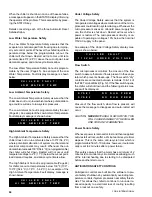
This message informs the operator of the nature of the
fault which occurred.
This message indicates the Return Water Temperature
at the time of the fault.
This message indicates the Leaving Water Temperature
at the time of the fault.
This display shows the Low Water Cutout (Leaving) which
was programmed at the time of the fault.
This display shows the Setpoint Temp which was pro-
grammed at the time of the fault.
This message indicates the Outdoor Ambient Tempera-
ture at the time of the fault.
This display shows the Low Ambient Cutout programmed
at the time of the fault.
This display shows the Low Pressure Cutout programmed
at the time of the fault.
This message indicates which system was in the lead
at the time of the fault.
O U T S I D E
A I R
T E M P
7 7 . 6
D E G F
L O W
A M B I E N T
C U T O U T
3 5 . 0
D E G F
L O W
P R E S S U R E
C U T O U T
4 4
P S I G
L E A D
S Y S T E M
S Y S
1
Содержание Millennium YCAJ150
Страница 21: ...FORM 150 65 NM4 21 YORK INTERNATIONAL LD02461 FIG 6 ELEMENTARY DIAGRAM Cont d...
Страница 22: ...22 YORK INTERNATIONAL ELEMENTARY DIAGRAM...
Страница 24: ...24 YORK INTERNATIONAL CONNECTION DIAGRAM FIG 7 CONNECTION DIAGRAM LD02463...
Страница 25: ...FORM 150 65 NM4 25 YORK INTERNATIONAL FIG 7 CONNECTION DIAGRAM Cont d LD02462...
Страница 26: ...26 YORK INTERNATIONAL CONNECTION DIAGRAM TERMINAL BOX AND SYSTEM WIRING FIG 8 SYSTEM WIRING LD02464...
Страница 28: ...28 YORK INTERNATIONAL CONNECTION DIAGRAM TERMINAL BOX AND SYSTEM WIRING FIG 8 SYSTEM WIRING Cont d LD02650...
Страница 30: ...30 YORK INTERNATIONAL FIG 8 SYSTEM WIRING Cont d LD02499...
Страница 100: ...100 YORK INTERNATIONAL LD02654 FIG 37B LOUVER BRACKETS INSTALLATION...
Страница 101: ...FORM 150 65 NM4 101 YORK INTERNATIONAL LD02655 FIG 37C GRILLE AND LOUVER INSTALLATION FRONT AND BACK...
Страница 103: ...FORM 150 65 NM4 103 YORK INTERNATIONAL LD02656 FIG 39A LOUVER INSTALLATION SIDES...
Страница 104: ...104 YORK INTERNATIONAL LD02654 FIG 39B LOUVER BRACKETS INSTALLATION...
Страница 105: ...FORM 150 65 NM4 105 YORK INTERNATIONAL LD02657 FIG 39C GRILLE AND LOUVER INSTALLATION FRONT AND BACK...
Страница 107: ...FORM 150 65 NM4 107 YORK INTERNATIONAL FIG 40A CONDENSER COIL LOUVER INSTALLATION SIDES LD02658...
Страница 108: ...108 YORK INTERNATIONAL FIG 40B CONDENSER COIL LOUVER INSTALLATION FRONT AND BACK LD02659...
Страница 110: ...110 YORK INTERNATIONAL FIG 41 REMOTE RESET BOARD LD02666 P1...