York Millennium YCAJ150 Скачать руководство пользователя страница 53

FORM 150.65-NM4

53

YORK INTERNATIONAL

water temperature drops into the CONTROL RANGE.
This may be required for small water loops. However, if
problems arise where the chiller does not load and pull
temperature down, select 0.1°F (0.05°C).

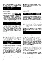
To program the RATE CONTROL TEMP, first press the
PROGRAM key. Repetitively press the ENTER key until
the display below appears.

Key in the desired value and press the ENTER key. The
new value will be entered into memory and the display
will advance to the next user programmable limit.

The micro will accept a range of programmable values
between 0.1 - 20°F (0.05 - 11.1°C).

NOTE: When programming values between 0.1 - 9.9°

(0.05 - 11.1°C), it is required to first key in a “0 “
or “00”. Example: 05.9°.

The next item which will require programming is the RATE
SENSITIVITY. The RATE SENSITIVITY is a means of
“overriding” the loading/unloading timers when water tem-
peratures are in the RATE CONTROL RANGE or the
CONTROL RANGE. This allows the micro to react to
abrupt downward changes in leaving or return water tem-
peratures. The ability to respond to “rate of change” varia-
tions in water temperatures gives the micro “anticipa-
tion” capabilities to reduce the possibility of “overshoot”
in leaving water temperature.

In demand limiting applications, to avoid cycling or to
avoid overshoot, RATE SENSITIVITY should be low. This
allows the micro to go into rate control to prevent loading
whenever water temperatures drop faster than the pro-
grammed RATE SENSITIVITY. Rate Control can go into
effect whenever water temperatures are in RATE CON-
TROL RANGE or the CONTROL RANGE. For these ap-
plications, a 3 - 5°F/min (1.7 - 2.8°C/min) RATE SENSI-
TIVITY is recommended. This may be required for small
water loops. However, if problems arise where the chiller
does not load and pull temperature down, select 5°F/
min (2.8°C/min).

NOTE: Too small of a RATE SENSITIVITY value se-

lection may prevent loading due to varying flows
or if the water system allows a slug of cold water
to enter which falsely fools the micro into think-
ing the RATE SENSITIVITY has been exceeded,
preventing loading and allowing leaving water tem-
perature to rise above the desired temperature.
In some cases, unloading or compressor shut-
down my result.

For normal comfort cooling, batch, or process applica-
tions, select a high RATE SENSITIVITY of 5°F/min (2.8°C/

R A T E

C O N T R O L

T E M P

=

1 0 . 0

F

The RATE CONTROL TEMP establishes a temperature
range (0.1 - 20°F [.05 - 11.1°C]) above the “Upper Limit
of CONTROL RANGE” where the micro will limit loading
or unload the system if the rate of change of water tem-
perature reduction exceeds the programmed RATE SEN-
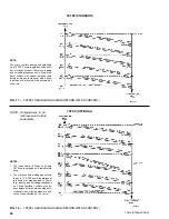
SITIVITY. In Fig. 14, a RATE CONTROL TEMP of 10°F
(5.5°C) is used.

In the CONTROL RANGE and RATE CONTROL RANGE
loading/unloading will normally occur according to devia-
tion from setpoint. “Rate Control” will function to prevent
loading if the water temperature change (leaving or re-
turn) exceeds the RATE SENSITIVITY, even though de-
viation from setpoint requires loading. This will reduce
the chance of overshoot.

Above THE RATE CONTROL TEMP RANGE the micro
will attempt to load the chiller every 60 seconds per stage.
This allows the chiller to gain control of the water tem-
perature as quickly as possible while still avoiding over-
shoot and limiting pulldown demand as temperature drops
and rate control is implemented.

Since RWT Control utilizes the buffering of the water
loop and a wide control (loading/unloading) range, com-
pressor/loader cycling is reduced, wear and tear on me-
chanical parts is reduced, and pulldown demand is au-
tomatically limited. This makes the selection of RATE
CONTROL TEMP and RATE SENSITIVITY values less
critical unless short water loops are encountered.

Before programming the RATE CONTROL TEMP, the user
should first determine if typically the normal fastest al-
lowable pulldowns are required or whether pulldown de-
mand limiting is desired. Programmable values from 00.1
- 20°F (0.05 - 11.1°C) are possible.

For normal pulldowns and quick response, a RATE
CONTROL TEMP of 0.1°F (0.05°C) is appropriate un-
less excessive overshoot is noted.

For demand limiting, energy efficiency and minimum
cycling, RATE CONTROL TEMPS of 10° - 20°F (5.6 -
11.1°C) are advisable with temperatures around 20°F
(11.1°C) most appropriate. This will cause the control to
react to water temperature rate of change well before the

FIG. 14 – RETURN WATER TEMPERATURE CONTROL

65°
(18.3°)

55°
(12.8°)

45°
(7.2°)

UPPER LIMIT OF RATE

CONTROL RANGE

UPPER LIMIT OF

CONTROL

RANGE (CR)

SETPOINT

ABOVE THE RATE CONTROL

TEMP RANGE

D

RATE CONTROL TEMP RANGE

(RATE CONTROL TEMP = 10°F [5.5°C])

E
D

CONTROL RANGE

(CR = 45 - 55°F [7.2 - 12.8°C])

E

BELOW THE CONTROL RANGE

Содержание Millennium YCAJ150

Страница 1: ...Supersedes See Back Page Form 150 65 NM4 198 MillenniumTM LIQUID CHILLERS AIR COOLED RECIPROCATING HERMETIC 60 HZ MODELS YCAJ150 230 200 230 460 3 60 26810A With EPROM 031 01652 001 Standard Brine Met...

Страница 2: ...67 Unit On Off Switch 74 Compressor Capacity Control 80 System Startup Checklist 81 Preventative Maintenance 86 Options 88 Troubleshooting Chart 106 Temperature Conversion Tables 110 GENERAL INFORMATI...

Страница 3: ...s are familiar with its potential hazards Shut off power supply to equipment before beginning work and follow lockout procedures When work ing inside equipment with power off take care to discharge ev...

Страница 4: ...MICRO PANEL COOLER CONTROL POWER SUPPLY POWER PANEL COMPRESSOR 1 COMPRESSOR 2 CONDENSER COIL S CONDENSER FANS SIGHT GLASSES HOT GAS BYPASS SYSTEM 1 SYSTEM 2 LIQUIDSTOP VALVE SYSTEM 1 FILTER DRIER SYST...

Страница 5: ...S COMPRESSOR TERMINAL BOX 8 CYLINDER MODEL J COMPRESSOR 27299A 27599A MOTOR TERMINALS SUPPRESSORS MOTOR PROTECTOR MP DISCHARGE STOP VALVE OILPRESSURE ACCESS CONN SIGHT GLASSES OIL CHARGING VALVE CAPAC...

Страница 6: ...rator is protected against freeze up to 20 F with an electrical heater cable as standard CAUTION Excessive flow will cause damage to the cooler Do not exceed max cooler GPM Special care should be take...

Страница 7: ...cted against freeze up to 28 9 C with an electrical heater cable as standard CAUTION Excessive flow will cause damage to the cooler Do not exceed max cooler flow Special care should be taken when mul...

Страница 8: ...8 NO OF FANS 36 Dia Direct Drive HP kWEach 1140 RPM 3 2 9 3 2 9 3 2 9 3 2 9 5 3 7 5 3 7 5 3 7 AIRFLOW TOTAL CFM 124 000 124 000 124 000 124 000 143 000 143 000 143 000 COOLER DUALCIRCUITED DWP 235PSIG...

Страница 9: ...8 8 8 8 8 NO OF FANS 914 mm Dia Direct Drive HP kWEach 1140 RPM 3 2 9 3 2 9 3 2 9 3 2 9 5 3 7 5 3 7 5 3 7 AIRFLOW TOTAL L S 58 522 58 522 58 522 58 522 67 489 67 489 67 489 COOLER DUALCIRCUITED 406mm...

Страница 10: ...de 12 walls should be no higher than the unit The area within the clearances and under the unit s must be kept clean of clutter Additional height should be included to allow for snow accumulation for...

Страница 11: ...an the unit The area within the clearances and under the unit s must be kept clean of clutter Additional height should be included to allow for snow accumulation for units which are expected to operat...

Страница 12: ...2 6 250 131 525 5 0 J150 58 151 200 250 200 200 225 2 6 250 105 420 4 9 151 200 250 200 200 225 2 6 250 105 420 4 9 J160 28 458 600 700 600 600 700 2 1 0 500 328 1278 12 0 376 450 600 400 450 500 2 1...

Страница 13: ...182 749 5 9 150 511 5 9 J230 46 578 700 800 600 2 2 600 3 3 0 500 228 936 8 1 228 936 8 1 J230 58 457 600 600 600 2 2 600 1 1 600 or 2 1 250 182 749 5 9 182 749 5 9 5 Wire Range is the minimum and ma...

Страница 14: ...801 5 0 300 350 164 801 5 0 J180 58 334 400 450 400 400 450 1 1 600 or 2 1 250 225 300 131 641 4 9 225 300 131 641 4 9 J190 28 894 1000 1200 1000 1000 1200 NA NA NA 376 1278 12 0 NA NA 328 1602 12 0 J...

Страница 15: ...CONTROL POWER SUPPLY UNIT PANEL COMPRESSOR POWER SUPPLY BY OTHERS LD01175 SEE NOTE 6 SEE NOTE 5 SINGLE POINT OPTION LD01174 R DISCONNECT OPTION SEE NOTE 5 UNIT PANEL G 2 L 2L3 2L2 2L1 1L1 1L2 1L3 BY...

Страница 16: ...Inspect unit for shipping damage 2 Rig unit per Fig 4 Remove unpainted shipping braces after installation 3 Open unit only to install water piping system Do not remove protective covers from water con...

Страница 17: ...t ing the unit to its foundation See DIMENSIONS pages 10 and 11 For ground level installations precautions should be taken to protect the unit from tampering by or injury to unau thorized persons Scre...

Страница 18: ...CP 2 31 CP 2 31 CP 2 31 CP 2 32 CP 2 31 CP 2 31 CP 2 31 CP 2 32 YCAJ230 CP 2 31 CP 2 31 CP 2 31 CP 2 32 CP 2 31 CP 2 31 CP 2 31 CP 2 32 ISOLATOR LOCATIONS VMC CP 2 X LD01089 NOTE Standard 1 25 4 mm de...

Страница 19: ...nd insulated to protect against freeze up during low ambient periods and to prevent forma tion of condensation on lines in warm humid climates 7 A chilled water flow switch either by YORK or oth ers M...

Страница 20: ...and 1 Device must have a minimum contact rating of 100VA at 115 volts A C 5 Contacts are rated at 115V 100VA resistive load only and must be suppressed at load by user 6 See installation operation an...

Страница 21: ...FORM 150 65 NM4 21 YORK INTERNATIONAL LD02461 FIG 6 ELEMENTARY DIAGRAM Cont d...

Страница 22: ...22 YORK INTERNATIONAL ELEMENTARY DIAGRAM...

Страница 23: ...ntactor auxiliary contacts must be sup pressed with YORK P N 031 00808 000 suppressor across the relay contactor coil Any contacts con nected to flow switch inputs or BAS inputs on terminals 13 19 or...

Страница 24: ...24 YORK INTERNATIONAL CONNECTION DIAGRAM FIG 7 CONNECTION DIAGRAM LD02463...

Страница 25: ...FORM 150 65 NM4 25 YORK INTERNATIONAL FIG 7 CONNECTION DIAGRAM Cont d LD02462...

Страница 26: ...26 YORK INTERNATIONAL CONNECTION DIAGRAM TERMINAL BOX AND SYSTEM WIRING FIG 8 SYSTEM WIRING LD02464...

Страница 27: ...FORM 150 65 NM4 27 YORK INTERNATIONAL CONNECTION DIAGRAM TERMINAL BOX AND SYSTEM WIRING FIG 8 SYSTEM WIRING Cont d LD02649...

Страница 28: ...28 YORK INTERNATIONAL CONNECTION DIAGRAM TERMINAL BOX AND SYSTEM WIRING FIG 8 SYSTEM WIRING Cont d LD02650...

Страница 29: ...FORM 150 65 NM4 29 YORK INTERNATIONAL CONNECTION DIAGRAM TERMINAL BOX AND SYSTEM WIRING FIG 8 SYSTEM WIRING Cont d LD02651...

Страница 30: ...30 YORK INTERNATIONAL FIG 8 SYSTEM WIRING Cont d LD02499...

Страница 31: ...oprocessor to main tain leaving water temperatures These decisions are a function of temperature deviation from setpoint and rate of change of temperature MICROPROCESSOR BOARD The Microprocessor Board...

Страница 32: ...ay and as safeties CURRENT TRANSFORMER C T A C T on the 3 power wiring of each motor sends AC signals proportional to motor current to the Power Sup ply Board which rectifies and filters the signal to...

Страница 33: ...ANEL 28697A KEYPAD MICROPROCESSOR BOARD TB3 LCD DISPLAY BOARD MICROPROCESSOR BOARD UNITON OFF SWITCH POWER SUPPLY BOARD 2T TRANSFORMER RELAY OUTPUT BOARD 1 LOCATION OF OPTIONAL RELAY OUTPUT BOARD 2 TB...

Страница 34: ...ressor running times number of compressor starts and option information on the chiller package This data is useful for monitoring chiller operation diagnosing potential future problems troubleshooting...

Страница 35: ...of the eight messages depending on the Dip Switch position A detailed explanation of the meaning of each message and a guide to programming the associated switch is provided on page 37 Fig 13 shows t...

Страница 36: ...N C O N T R O L S H A R E D C O N D E N S E R F A N C O N T R O L E N G L I S H U N I T S R E A D O U T M E T R I C U N I T S R E A D O U T R E T U R N W A T E R C O N T R O L L E A V I N G W A T E R...

Страница 37: ...10 C A low ambient kit MUST be installed if the switch is placed in this position SWITCH 3 OPEN This mode allows a Remote Control Center or an ISN panel to only view chiller operating conditions It wi...

Страница 38: ...eri enced See page 93 for fan control sequence NOTE Discharge pressure transducers must be in stalled These are optional Discharge Pressure Read out Option unless a Low Ambient Kit is installed SWITCH...

Страница 39: ...operator to de termine current chiller operating status as a whole and as individual systems The messages displayed will include running status cooling demand fault status external cy cling device st...

Страница 40: ...ll take place when discharge pressure has dropped 60 PSIG 4 1 bar below the threshold Optional discharge pressure transducers must be in stalled for this feature to operate This is accomplished by add...

Страница 41: ...H A M B I E N T T E M P S Y S 1 L O W O I L P R E S S S Y S 2 L O W O I L P R E S S C H I L L E R F A U L T 1 1 5 V A C U N D E R V O L T A G E S Y S 1 H I G H O I L T E M P S Y S 2 H I G H O I L T E...

Страница 42: ...ances the day when the SET TIME display is being programmed The day is nor mally advanced to correspond to the current day of the week The day will advance a day at a time each time the key is pressed...

Страница 43: ...ut For this cut out to be functional the Discharge Pressure Readout Option must be installed GENERAL Pushing the PROGRAM key allows the user to program 11 system operating limits These limits include...

Страница 44: ...he high ambient cut out point If the ambient rises above this point the chiller will shut down Restart can occur when temperature drops below the cut out This only applies to outdoor air cooled chille...

Страница 45: ...for 4 F 2 2 C below the desired leaving chilled liquid temperature AVERAGE CURRENT UNLOAD The purpose of AVERAGE CURRENT UNLOAD is to pro vide adequate motor cooling and to prevent the motor from fau...

Страница 46: ...ATE CONTROL TEMP RANGE In this range if water temperature is dropping faster than the RATE SENSITIVITY setting the micro will not load any more stages because water temperature is dropping quickly Thi...

Страница 47: ...the week is displayed The day will advance each time the key is pressed The cursor will already be below the first digit of the time Key in the new time if required Be sure to key in a 0 before the o...

Страница 48: ...hed ule This can be done manually for each day or by press ing CANCEL and ENTER when the MONDAY START STOP schedule appears NOTE This will have no effect on the holiday schedule Continue to program ea...

Страница 49: ...dentally the microproces sor will automatically return to the Daily Schedule MANUAL OVERRIDE M A N U A L O V E R R I D E Manual Override When the MANUAL OVERRIDE key is pressed the Daily Schedule prog...

Страница 50: ...ability to select the type of chilled liq uid temperature control by choosing either Return or Leaving Temperature Control This provides the ability to fine tune the method of control for comfort coo...

Страница 51: ...50 for instructions to reprogram the Mi croprocessor Dip Switch S1 Switch 4 The display will then scroll to a second message hold This message will display the user s Design Leaving Water Temperature...

Страница 52: ...5 F 7 2 12 8 C CONTROL RANGE A RATE CONTROL TEMP OF 65 F 18 3 C which is typi cal 10 F 5 5 C above the high end the Control Range is shown temperatures provide a Control Range differential of 54 0 44...

Страница 53: ...lt For normal comfort cooling batch or process applica tions select a high RATE SENSITIVITY of 5 F min 2 8 C R A T E C O N T R O L T E M P 1 0 0 F The RATE CONTROL TEMP establishes a temperature range...

Страница 54: ...ery high rate to exceed the RATE SENSITIVITY value pro grammed This will assure normal loading will occur 5 F min 2 8 C min also works well in comfort cooling appli cations If unsure of a RATE SENSITI...

Страница 55: ...oading and Rate Control will follow PROGRAMMING LEAVING WATER RATE CONTROL Programmable RATE CONTROL is designed to limit com pressor loader cycling thus saving energy and reducing wear on mechanical...

Страница 56: ...the ENTER key The new value will be entered into memory and the display will advance to the next user programmable limit than 1X the Rate Sensitivity Otherwise no other loading or unloading will resu...

Страница 57: ...1 C below the temperature at which it was loaded assuming unload ing timers and rate control software allows Listed in Fig 17 19 are the loading and unloading se quences for 5 7 and 10 steps of contr...

Страница 58: ...between stages increased when miss ing steps are activated or deactivated by the micro NOTES 1 The Lead Comp 2 Steps Lag Comp Off Step is skipped on a temperature drop 2 The micro controls loading and...

Страница 59: ...FORM 150 65 NM4 59 YORK INTERNATIONAL 10 STEP OPTIONAL FIG 19 10 STEP LOADING UNLOADING RETURN WATER CONTROL LD02660 NOTE Temperatures in parentheses are Celsius equivalents...

Страница 60: ...F 1 LEAD COMP UNLOADED LAG COMP OFF LEAD COMP UNLOADED LAG COMP OFF LEAD COMP OFF LAG COMP OFF LEAD COMP OFF LAG COMP OFF TEMPERATURE FALL 7 STEP OPTIONAL TEMPERATURE RISE LOAD UNLOAD 7 LEAD COMP 2 ST...

Страница 61: ...PSIG 2 8 mPa the contacts in the high pressure cut out will open which removes 115VAC from the motor protector mod ule When 115VAC control power is lost to the module the module s MP contacts open bre...

Страница 62: ...ection Page 61 Auto restart will be permitted after a shutdown when dis charge pressure drops to below 330 PSIG 2 3 mPa which allows the mechanical high pressure cut out to reset and its contacts to c...

Страница 63: ...r in a short time period An ex ample would be if ambient temperature dropped below the cut out temperature would have to rise 5 F 2 8 C above the cut out before the fault lockout would clear and resta...

Страница 64: ...lockout on a safety When the chiller is shut down on one of these safeties a message will appear on the STATUS display informing the operator of the problem This is accessible by press ing the STATUS...

Страница 65: ...start Even though the Anti recycle timer has timed out a minimum of 2 minutes 2 minute start up timer must always elapse after a compressor stop be fore it may again restart If a power failure occurs...

Страница 66: ...ssumes the lead The previous running compressor will now have 120 pumpdowns available S Y S 1 P U M P D O W N F A I L S Y S 2 P U M P D O W N F A I L A pumpdown failure fault will occur if a system pe...

Страница 67: ...ased from memory A sample printout is shown in Fig 21 Photo PRINT KEYS FIG 21 OPERATING DATA PRINTOUT YORK INTERNATIONAL CORPORATION RECIPROCATING WATER CHILLERS SYSTEMSTATUS 8 45AM 6 3 98 SYS 1 COMPR...

Страница 68: ...UTDOWNNUMBER3 SHUTDOWN 8 47AM 6 3 98 SYS1STATUS NOFAULTS SYS2 MOTORCURRENTSHUTDOWN RETURNWATERTEMP 65 0 DEGF LEAVINGWATERTEMP 54 0 DEGF LOWWATERCUTOUT 36 0 DEGF SETPOINTTEMP 45 0 DEGF OUTSIDEAIRTEMP 7...

Страница 69: ...ystem is presently on as a result of com mands from the microprocessor This is a coded number and the steps must be decoded to be meaningful The decoding varies according to the number of stages pro g...

Страница 70: ...D E G F M I N L E A D S Y S T E M I S S Y S T E M N U M B E R 1 E V A P O R A T O R W A T E R P U M P S T A T U S O N E V A P O R A T O R H E A T E R S T A T U S O F F C O N D E N S E R W A T E R P U...

Страница 71: ...ng the ENTER key will allow the operator to scroll through the information available in the SAFETY SHUTDOWN Buffer In the information that follows a sample message along with an explanation is provide...

Страница 72: ...of the fault This message indicated the entering condenser water temperature at the time of the fault A fixed value will be displayed if the optional sensor is not installed This message indicates the...

Страница 73: ...E O N S Y S 2 R U N P E R M I S S I V E O N S Y S 2 L O A D I N G S T A G E S 1 S Y S 2 F O R W A R D F A N S O F F S Y S 2 S U C T I O N P R E S S 6 2 P S I G S Y S 2 R E V E R S E F A N S O F F S Y...

Страница 74: ...R M ALARM CONTACTS ANNUNCIATION ALARM Dry contacts connected to terminals 23 and 24 Fig 24 are supplied which will transition to function as a warning whenever a fault shutdown occurs on any sys tem o...

Страница 75: ...le Timers timed out the compressor with the lowest run hours will start first 3 If both compressors are waiting to start Anti recycle Timers are not timed out the micro will assign the lead to the com...

Страница 76: ...or manual lead lag selection is wired into terminals 13 and 19 on the TB3 Terminal block The location of these terminals is shown in Fig 25 FIG 25 LEAD LAG CONTACT CONNECTION LOCATION LD02093 26001A F...

Страница 77: ...e the new value in memory S Y S 1 N O R U N P E R M S Y S 2 N O R U N P E R M R E M S E T P O I N T 4 0 0 R E M R A N G E 2 0 D E G F ing requirements In addition the low battery message which is disp...

Страница 78: ...sed with a user supplied YORK P N 031 00808 suppressor NOTE Remote Setpoint Reset will not operate when a Remote Control Center Option Kit is connected to the Micro Panel The Remote Control Center wil...

Страница 79: ...l turn on 4 seconds after the compressor starts These fans will continue to run until the compressor shuts down These fans are designated as Fans 2 4 on SYS 1 and Fans 6 8 on SYS 2 If the ambient temp...

Страница 80: ...to the suction plenum This forces the piston up uncovering the re cessed opening which allows the suction gas to flow through the port and into the cylinders The cylinders are now loaded NOTE 6 cylind...

Страница 81: ...t load operating conditions it is not abnormal for the oil level to be in the lower sight glass If it is necessary to add oil con nect a YORK oil pump to the oil charging valve but do not tighten the...

Страница 82: ...After several min utes of operation the bubbles will disappear and there will be a solid column of liquid when the unit is operating normally On startup foaming of the oil may be evident in the compre...

Страница 83: ...If however an adjustment is to be made the expansion valve adjusting screw should be turned not more than one turn at a time allowing suffi cient time approximately 15 minutes between adjust ments for...

Страница 84: ...if cooling demand requires temperature and rate control The lag compressor remains unchanged at the 1st step of loading 15 After 7 minutes of run time the lag compres sor will load to its 2nd step of...

Страница 85: ...two steps to its 1st step of 3 loading steps 12 After 10 minutes and 4 seconds of run time the motor current of the lag compressor must be 14 FLA and 115 FLA Oil pressure must be 5 PSID 34 5 kPa If th...

Страница 86: ...new appearance for a reasonable length of operating time Discolora tion of the oil either turning darker brown or in some cases lighter is an indication of contamination ba sically due to moisture If...

Страница 87: ...lve and pump oil into the crankcase to the proper level It is necessary that the suc tion end of the hand oil pump be kept submerged under the oil level in the container at all times to avoid entrance...

Страница 88: ...Connections to this contact can be made on Terminals 21 and 22 of TB1 in the power panel The location of these terminals is shown in Fig 29 This option utilizes a second Relay Output Board and associ...

Страница 89: ...ser as required Re verse rotation of the fans is accomplished by the addi tion of reversing contactors Components The Low Ambient Option consists of 3 kits a Low Ambi ent Kit selected from the chart b...

Страница 90: ...3 SYS 1 5M 7M or fans 5 7 SYS 2 11M 13M and will operate the corresponding fans in the forward direction whenever discharge pressure ex ceeds 360 PSIG 2 5 mPa These fans will stay on until discharge...

Страница 91: ...g valve with an integral solenoid The pilot operated solenoid is controlled by the microprocessor according to water temperature The regulating valve which becomes activated when the solenoid is energ...

Страница 92: ...ULCR CR CR 10 Where UCLR Upper Limit of Control Range CR Control Range Differential Example 55 12 8 C 10 10 10 46 F 7 8 C If temperature continues to drop while the Hot Gas is energized the Hot Gas w...

Страница 93: ...arge pressure only allows higher discharge pres sures which in turn raises suction pressure by permit ting better operation of the thermal expansion valve To convert to discharge pressure cycling the...

Страница 94: ...of the keypad In addition to manual print selection the micro panel will provide an automatic printout whenever a fault occurs An explanation of the keypad use to obtain a print out is discussed in th...

Страница 95: ...tout is shown in Fig 21 on page 67 A printout of the fault shutdown history may be obtained by pressing the HISTORY key A printout showing the last 3 faults with all system conditions at the time of t...

Страница 96: ...t Before starting installation all of the items in the kit should be identified by comparing with Fig 36 2 All holes for mounting kit parts are provided in both the chiller frame and the added support...

Страница 97: ...FORM 150 65 NM4 97 YORK INTERNATIONAL LD02652 FIG 36 WIRE GRILLE INSTALLATION NOTE Notch grilles to suit water connections and wiring harnesses...

Страница 98: ...re starting installation all of the items in the kit should be identified by comparing with Fig 37a 37b and 37c 2 All holes for mounting kit parts are provided in both the chiller frame and the added...

Страница 99: ...FORM 150 65 NM4 99 YORK INTERNATIONAL FIG 37A GRILLE AND LOUVER INSTALLATION SIDES LD02653 NOTE Notch grilles to suit water connections and wiring harnesses...

Страница 100: ...100 YORK INTERNATIONAL LD02654 FIG 37B LOUVER BRACKETS INSTALLATION...

Страница 101: ...FORM 150 65 NM4 101 YORK INTERNATIONAL LD02655 FIG 37C GRILLE AND LOUVER INSTALLATION FRONT AND BACK...

Страница 102: ...ation Before starting installation all of the items in the kit should be identified by comparing with Figs 39a 39b and 39c and the associated parts lists 2 All holes for mounting kit parts are provide...

Страница 103: ...FORM 150 65 NM4 103 YORK INTERNATIONAL LD02656 FIG 39A LOUVER INSTALLATION SIDES...

Страница 104: ...104 YORK INTERNATIONAL LD02654 FIG 39B LOUVER BRACKETS INSTALLATION...

Страница 105: ...FORM 150 65 NM4 105 YORK INTERNATIONAL LD02657 FIG 39C GRILLE AND LOUVER INSTALLATION FRONT AND BACK...

Страница 106: ...ry mounting hardware Installation 1 Refer to Fig 40a and 40b and the associated parts list Before starting installation all of the items in the kit should be identified by comparing with Fig 40a and 4...

Страница 107: ...FORM 150 65 NM4 107 YORK INTERNATIONAL FIG 40A CONDENSER COIL LOUVER INSTALLATION SIDES LD02658...

Страница 108: ...108 YORK INTERNATIONAL FIG 40B CONDENSER COIL LOUVER INSTALLATION FRONT AND BACK LD02659...

Страница 109: ...signal should be connected to the and terminals on the TB3 Terminal Block at the right of the Microprocessor Board Be sure polarity is correct CAUTION THE 0 10VDC INPUT SIGNAL WIRING MUST NOT BE EARTH...

Страница 110: ...110 YORK INTERNATIONAL FIG 41 REMOTE RESET BOARD LD02666 P1...

Страница 111: ...motor protector wiring and motor problems As sure that motor protector is not tripped due Motor contactor may to external high pressure switch or may not energize 3 Defective relay output board 3 Repl...

Страница 112: ...mometer will result is 10 F 5 5 C Chiller Fault High 1 Temperature sensed incorrectly 1 Verify actual ambient temperature at probe Ambient Temp by thermistor 10 F 5 5 C with a thermometer placed Cuts...

Страница 113: ...in either sight Level glass at all times Add YORK C oil if Particularly at necessary start up 2 Excessive flood back of liquid 2 Adjust Thermal Expansion Valve TXV or refrigerant replace power elemen...

Страница 114: ...ensor vs thermometer of 2 F is not unusual Replace if necessary 7 Defective evaporator or optional 7 Replace transducer after verifying with a discharge transducer gauge Lack of Cooling 1 Fouled evapo...

Страница 115: ...43 9 111 231 8 44 4 112 233 6 45 0 113 235 4 45 6 114 237 2 46 1 115 239 0 46 7 116 240 8 47 2 117 242 6 47 8 118 244 4 48 3 119 246 2 48 9 120 248 0 49 4 121 249 8 50 0 122 251 6 50 6 123 253 4 51 1...

Страница 116: ...pic Team 36USC380 P O Box 1592 York Pennsylvania USA 17405 1592 Subject to change without notice Printed in USA Copyright by York International Corporation 1998 ALL RIGHTS RESERVED Form 150 65 NM4 198...

Отзывы: