


FORM 150.65-NM4
89
YORK INTERNATIONAL
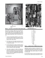
Connections to this contact can be made on Terminals
25 and 26 of TB1 in the power panel. The location of
these terminals is shown in Fig. 30.
If a power failure occurs which shuts the entire chiller
down, the contacts will not be allowed to close again
until 30 seconds after power is restored. This prevents
rapid cycling of the chilled water pump.
This option utilizes a second Relay Output Board and
associated wiring. The part number for the Field Mounted
Pump Control Kit is 471-01232-101. This kit is not re-
quired if a second Relay Output Board is already installed.
NOTE: Any inductive devices (contactor/relay coil) con-
nected to these contacts must be suppressed
with YORK P/N 031-00808 supplied by others.
Otherwise, nuisance faults may occur.
0°F LOW AMBIENT OPTION
The standard chiller is designed to operate in an ambi-
ent of 25°F (-6.7°C) or higher. If it is necessary to oper-
ate the chiller in an ambient between 0° and 25°F (-17.8
and -3.9°C), the chiller should be purchased with the
factory installed Low Ambient Option.
NOTE: Occasional operation below 0°F (-17.8°C) is nor-
mally possible. In these cases, a low suction
pressure shutdown may sometimes occur, but
can usually be tolerated.
Operation
The fundamental purpose of the Low Ambient Option is
to reduce the capacity of the condenser when the ambi-
ent temperature is in the 0° to 25°F (-17.8 to -3.9°C)
range. This assures that adequate discharge pressures
can be maintained at low temperatures which will elimi-
nate low suction pressure faults.
Operation at low ambients is accomplished by cycling
fans according to discharge pressure. This requires the
addition of discharge pressure transducers which allows
the microprocessor to add two additional steps of con-
trol to the standard fan control scheme. Fans are now
allowed to cycle completely off, and two fans on each
system are permitted to run in the reverse direction. This
reduces the capacity of the condenser as required. Re-
verse rotation of the fans is accomplished by the addi-
tion of reversing contactors.
Components
The Low Ambient Option consists of 3 kits: a Low Ambi-
ent Kit selected from the chart below, a 471-01232-131
Discharge Pressure Readout Kit, and also a 471-01232-
101 Relay Board Kit. All three kits are required. The Relay
Board Kit is not required if two Relay Boards are already
present in the panel.
When the Low Ambient Option is installed, the following
physical changes are made to the standard chiller:
1.
Discharge pressure transducers & wiring are added.
2.
Reversing contactors 9M, 10M, 15M and 16M with
supporting wiring are added.
3.
A second Relay Output Board and wiring is installed.
Programming
The control panel may be programmed for “AMBIENT &
DISCH PR FAN CONTROL” (Ambient & discharge pres-
sure fan control) or by “DISCHARGE PRESSURE FAN
CONTROL” (fan control by discharge pressure only). This
is selected by placing SW. 8 on the Microprocessor to
the appropriate position. See page 38.
LOW AMBIENT KIT PART NUMBERS
MODEL
CHILLER WITH
CHILLER WITH
NUMBER
STANDARD FANS
LOW NOISE
FAN OPTION
YCAJ150-17
371-02204-161
371-02204-161
YCAJ150-28
371-02204-161
371-02204-161
YCAJ150-40
371-02204-162
371-02204-162
YCAJ150-46
371-02204-163
371-02204-167
YCAJ150-58
371-02204-163
371-02204-163
YCAJ160-28
371-02204-161
371-02204-161
YCAJ160-40
371-02204-162
371-02204-162
YCAJ160-46
371-02204-163
371-02204-167
YCAJ160-58
371-02204-163
371-02204-163
YCAJ180-28
371-02204-161
371-02204-161
YCAJ180-40
371-02204-162
371-02204-162
YCAJ180-46
371-02204-163
371-02204-167
YCAJ180-58
371-02204-163
371-02204-163
YCAJ190-28
371-02204-161
371-02204-161
YCAJ190-40
371-02204-162
371-02204-162
YCAJ190-46
371-02204-163
371-02204-167
YCAJ190-58
371-02204-163
371-02204-163
YCAJ200-28
371-02204-164
371-02204-161
YCAJ200-40
371-02204-165
371-02204-162
YCAJ200-46
371-02204-166
371-02204-167
YCAJ200-58
371-02204-162
371-02204-163
YCAJ220-40
371-02204-165
371-02204-162
YCAJ220-46
371-02204-166
371-02204-167
YCAJ220-58
371-02204-162
371-02204-163
YCAJ230-40
371-02204-165
371-02204-162
YCAJ230-46
371-02204-166
371-02204-167
YCAJ230-58
371-02204-162
371-02204-163
Содержание Millennium YCAJ150
Страница 21: ...FORM 150 65 NM4 21 YORK INTERNATIONAL LD02461 FIG 6 ELEMENTARY DIAGRAM Cont d...
Страница 22: ...22 YORK INTERNATIONAL ELEMENTARY DIAGRAM...
Страница 24: ...24 YORK INTERNATIONAL CONNECTION DIAGRAM FIG 7 CONNECTION DIAGRAM LD02463...
Страница 25: ...FORM 150 65 NM4 25 YORK INTERNATIONAL FIG 7 CONNECTION DIAGRAM Cont d LD02462...
Страница 26: ...26 YORK INTERNATIONAL CONNECTION DIAGRAM TERMINAL BOX AND SYSTEM WIRING FIG 8 SYSTEM WIRING LD02464...
Страница 28: ...28 YORK INTERNATIONAL CONNECTION DIAGRAM TERMINAL BOX AND SYSTEM WIRING FIG 8 SYSTEM WIRING Cont d LD02650...
Страница 30: ...30 YORK INTERNATIONAL FIG 8 SYSTEM WIRING Cont d LD02499...
Страница 100: ...100 YORK INTERNATIONAL LD02654 FIG 37B LOUVER BRACKETS INSTALLATION...
Страница 101: ...FORM 150 65 NM4 101 YORK INTERNATIONAL LD02655 FIG 37C GRILLE AND LOUVER INSTALLATION FRONT AND BACK...
Страница 103: ...FORM 150 65 NM4 103 YORK INTERNATIONAL LD02656 FIG 39A LOUVER INSTALLATION SIDES...
Страница 104: ...104 YORK INTERNATIONAL LD02654 FIG 39B LOUVER BRACKETS INSTALLATION...
Страница 105: ...FORM 150 65 NM4 105 YORK INTERNATIONAL LD02657 FIG 39C GRILLE AND LOUVER INSTALLATION FRONT AND BACK...
Страница 107: ...FORM 150 65 NM4 107 YORK INTERNATIONAL FIG 40A CONDENSER COIL LOUVER INSTALLATION SIDES LD02658...
Страница 108: ...108 YORK INTERNATIONAL FIG 40B CONDENSER COIL LOUVER INSTALLATION FRONT AND BACK LD02659...
Страница 110: ...110 YORK INTERNATIONAL FIG 41 REMOTE RESET BOARD LD02666 P1...