


56
YORK INTERNATIONAL
NOTE: When programming values between 0.1 - 9.9°,
it is required to first key in a “0” or “00”. Ex-
ample: 05.9°.
The next item which will require programming is the RATE
SENSITIVITY.
The RATE SENSITIVITY is a means of “overriding” the
loading/unloading timers when water temperatures are
in the RATE CONTROL RANGE or the CONTROL
RANGE. This allows the micro to react to abrupt down-
ward changes in leaving or return water temperatures.
The ability to respond to “rate of change” variations in
water temperatures gives the micro “anticipation” capa-
bilities to reduce the possibility of “overshoot” in leaving
water temperature.
In demand limiting applications, to avoid cycling, or to
avoid overshoot, RATE SENSITIVITY should be low. This
allows the micro to go into rate control to prevent loading
or cause unloading whenever water temperatures drop
faster than the programmed RATE SENSITIVITY. Rate
Control can go into effect whenever water temperatures
are in RATE CONTROL RANGE or the CONTROL
RANGE. For these applications, a 3 - 5.0°F/min (1.7 -
2.8°C/min). RATE SENSITIVITY is recommended. This
may be needed for small water loops. However, if prob-
lems arise where the chiller does not load or abruptly
turns a compressor off and fails to pull temperature down,
select 5.0°F/min (2.8°C/min).
NOTE: Too small of a RATE SENSITIVITY Selection
may prevent loading due to varying flows or if the
water system allows a slug of cold water to enter
which falsely fools the micro into thinking the
RATE SENSITIVITY has been exceeded, pre-
venting loading and allowing leaving water tem-
perature to rise above the desired temperature.
For normal comfort cooling, batch, or process applica-
tions, select a high RATE SENSITIVITY of 5.0°F/min
(2.8°C/min). Before Rate Control can go into effect, the
water temperature would have to change at a very high
rate to exceed the RATE SENSITIVITY value pro-
grammed. This will assure normal loading will occur at
the fastest possible speed. In most applications, 5.0°F/
min (2.8°C/min). is suggested. If unsure of a RATE
SENSITIVITY selection, use 5.0°F/min (2.8°C/min).
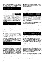
To program the RATE SENSITIVITY, first press the PRO-
GRAM key. Repetitively press the ENTER key until the
display below appears.
Key in the desired value and press the ENTER key. The
new value will be entered into memory and the display
will advance to the next user programmable limit.
than 1X the Rate Sensitivity. Otherwise, no other loading
or unloading will result in this temperature range.
In the upper half of the Control Range between the TAR-
GET and the High Limit of the Control Range and in the
Rate Control Range, loading will take place in 150 sec.
intervals until temperature drops below the TARGET tem-
perature. The Rate Control software may prevent loading
or initiate unloading if temperature drops faster than 2X
the programmed Rate Sensitivity.
Above the RATE CONTROL TEMP RANGE, the micro
will attempt to load the chiller as fast as it can (150
seconds per stage). This allows the chiller to gain con-
trol of the water temperature as quickly as possible while
still avoiding overshoot and limiting pulldown demand as
temperature drops and rate control is implemented.
Since LWT Control does not have the water loop for buff-
ering after a load/unload response and utilizes a narrow
control (loading/unloading) range, compressor/loader
cycling can be a problem. This makes the selection of
RATE CONTROL TEMP and RATE SENSITIVITY values
very critical.
Before programming the RATE CONTROL TEMP, the user
should first determine if typically the fastest allowable
pulldowns are required or whether pulldown demand lim-
iting is desired. Programmable values from 0.1 - 20° F
(0.05 - 11.1°C) are possible.
For normal pulldowns and quick response, a RATE
CONTROL TEMP of 0.1°F (0.05°C) is appropriate un-
less excessive overshoot is noted.
For demand limiting, energy efficiency, elimination of
overshoot, and minimum cycling, RATE CONTROL
TEMPS of 10 - 20°F (5.6 - 11.1°C) are advisable. This
will cause the controls to react to water temperature rate
of change well before the water temperature drops into
the CONTROL RANGE. This may be required for small
water loops. However, if problems arise where the chiller
does not load and pull temperature down, select 0.1°F
(0.05°C).
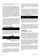
To program the RATE CONTROL TEMP, first press the
PROGRAM key. Repetitively press the ENTER key until
the display below appears.
Key in the desired value and press the ENTER key. The
new value will be entered into memory and the display
will advance to the next user programmable limit.
The micro will accept a range of programmable values
between 0.1 - 20°F (0.05 - 11.1°C).
R A T E
C O N T R O L
T E M P
=
1 0 . 0
F
R A T E
S E N S I T I V I T Y
=
5 . 0
F / M I N .
Содержание Millennium YCAJ150
Страница 21: ...FORM 150 65 NM4 21 YORK INTERNATIONAL LD02461 FIG 6 ELEMENTARY DIAGRAM Cont d...
Страница 22: ...22 YORK INTERNATIONAL ELEMENTARY DIAGRAM...
Страница 24: ...24 YORK INTERNATIONAL CONNECTION DIAGRAM FIG 7 CONNECTION DIAGRAM LD02463...
Страница 25: ...FORM 150 65 NM4 25 YORK INTERNATIONAL FIG 7 CONNECTION DIAGRAM Cont d LD02462...
Страница 26: ...26 YORK INTERNATIONAL CONNECTION DIAGRAM TERMINAL BOX AND SYSTEM WIRING FIG 8 SYSTEM WIRING LD02464...
Страница 28: ...28 YORK INTERNATIONAL CONNECTION DIAGRAM TERMINAL BOX AND SYSTEM WIRING FIG 8 SYSTEM WIRING Cont d LD02650...
Страница 30: ...30 YORK INTERNATIONAL FIG 8 SYSTEM WIRING Cont d LD02499...
Страница 100: ...100 YORK INTERNATIONAL LD02654 FIG 37B LOUVER BRACKETS INSTALLATION...
Страница 101: ...FORM 150 65 NM4 101 YORK INTERNATIONAL LD02655 FIG 37C GRILLE AND LOUVER INSTALLATION FRONT AND BACK...
Страница 103: ...FORM 150 65 NM4 103 YORK INTERNATIONAL LD02656 FIG 39A LOUVER INSTALLATION SIDES...
Страница 104: ...104 YORK INTERNATIONAL LD02654 FIG 39B LOUVER BRACKETS INSTALLATION...
Страница 105: ...FORM 150 65 NM4 105 YORK INTERNATIONAL LD02657 FIG 39C GRILLE AND LOUVER INSTALLATION FRONT AND BACK...
Страница 107: ...FORM 150 65 NM4 107 YORK INTERNATIONAL FIG 40A CONDENSER COIL LOUVER INSTALLATION SIDES LD02658...
Страница 108: ...108 YORK INTERNATIONAL FIG 40B CONDENSER COIL LOUVER INSTALLATION FRONT AND BACK LD02659...
Страница 110: ...110 YORK INTERNATIONAL FIG 41 REMOTE RESET BOARD LD02666 P1...