


80
YORK INTERNATIONAL
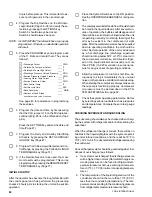
COMPRESSOR CAPACITY CONTROL
FIG. 28 – COMPRESSOR UNLOADING SEQUENCE
CHILLER
# OF
# OF
MODEL
SYSTEM
CYLINDERS
UNLOADING STEPS
YCA
STANDARD OPTIONAL
J150
1
6
J160
2
6
5
7
J180
J190
1
8
5
8
2
6
J200
J220
1 & 2
8
5
10
J230
6 CYLINDER
8 CYLINDER
The function of the compressor capacity control system
is to automatically adjust the compressor pumping ca-
pacity to balance with the cooling load at a pre-deter-
mined return water temperature and to permit the com-
pressor to start under partial load. The compressor ca-
pacity control system is actuated by means of gas pres-
sure from the discharge side of the compressor. Gas
pressure to the unloader piston unloads the associated
cylinders, and release of this pressure loads them. Con-
trol of the gas pressure to the unloader elements is the
fuction of the compressor capacity control solenoids.
UNLOADING
When the solenoid valve is energized, discharge gas pres-
sure is applied to the top of the unloader piston, forcing
it down. The bottom end of the piston seats against the
recessed opening to the suction plenum, effectively block-
ing the flow of suction gas into the cylinders (blocked
suction unloading). The cylinders are now unloaded.
LOADING
When the solenoid valve is de-energized, gas pressure
on top of the unloader piston is relieved to the suction
plenum. This forces the piston up, uncovering the re-
cessed opening which allows the suction gas to flow
through the port and into the cylinders. The cylinders
are now loaded.
NOTE:
6-cylinder compressors are equipped with 3 cylinder
banks. Cylinders 3 & 4 are permanently loaded cylin-
ders and have no unloading solenoids. If “optional” un-
loading is supplied, cylinders 1 & 2 are the first cylin-
ders to load while cylinders 5 & 6 the last to load. This
provides three steps of compressor loading/unloading.
Unloading occurs in the reverse sequence. In the “stan-
dard” loading/unloading scheme where the compressor
has 2 steps of loading/unloading, the wiring to the un-
loading solenoid for cylinders 1 & 2 is unconnected,
effectively making 1 & 2 permanently loaded cylinders.
8-cylinder compressors are equipped with 4 cylinder
banks. Cylinders 1 & 2 are permanently loaded cylin-
ders and have no unloading solenoids. If “optional” un-
loading is supplied, cylinders 5 & 6 are the first cylin-
ders to load, cylinders 3 & 4 the next to load, and 7 & 8
the last to load. This provides 4 steps of loading/unload-
ing. Unloading occurs in the reverse sequence. In the
“standard” loading/unloading scheme where the com-
pressor has 2 steps of loading/unloading, the wiring to
the unloading solenoids for cylinders 5 & 6 is uncon-
nected, effectively making 5 & 6 permanently loaded
solenoids. In addition, the solenoids for cylinders 3 & 4
and solenoids for cylinders 7 & 8 are wired together to
function as a single step of loading/unloading.
Содержание Millennium YCAJ150
Страница 21: ...FORM 150 65 NM4 21 YORK INTERNATIONAL LD02461 FIG 6 ELEMENTARY DIAGRAM Cont d...
Страница 22: ...22 YORK INTERNATIONAL ELEMENTARY DIAGRAM...
Страница 24: ...24 YORK INTERNATIONAL CONNECTION DIAGRAM FIG 7 CONNECTION DIAGRAM LD02463...
Страница 25: ...FORM 150 65 NM4 25 YORK INTERNATIONAL FIG 7 CONNECTION DIAGRAM Cont d LD02462...
Страница 26: ...26 YORK INTERNATIONAL CONNECTION DIAGRAM TERMINAL BOX AND SYSTEM WIRING FIG 8 SYSTEM WIRING LD02464...
Страница 28: ...28 YORK INTERNATIONAL CONNECTION DIAGRAM TERMINAL BOX AND SYSTEM WIRING FIG 8 SYSTEM WIRING Cont d LD02650...
Страница 30: ...30 YORK INTERNATIONAL FIG 8 SYSTEM WIRING Cont d LD02499...
Страница 100: ...100 YORK INTERNATIONAL LD02654 FIG 37B LOUVER BRACKETS INSTALLATION...
Страница 101: ...FORM 150 65 NM4 101 YORK INTERNATIONAL LD02655 FIG 37C GRILLE AND LOUVER INSTALLATION FRONT AND BACK...
Страница 103: ...FORM 150 65 NM4 103 YORK INTERNATIONAL LD02656 FIG 39A LOUVER INSTALLATION SIDES...
Страница 104: ...104 YORK INTERNATIONAL LD02654 FIG 39B LOUVER BRACKETS INSTALLATION...
Страница 105: ...FORM 150 65 NM4 105 YORK INTERNATIONAL LD02657 FIG 39C GRILLE AND LOUVER INSTALLATION FRONT AND BACK...
Страница 107: ...FORM 150 65 NM4 107 YORK INTERNATIONAL FIG 40A CONDENSER COIL LOUVER INSTALLATION SIDES LD02658...
Страница 108: ...108 YORK INTERNATIONAL FIG 40B CONDENSER COIL LOUVER INSTALLATION FRONT AND BACK LD02659...
Страница 110: ...110 YORK INTERNATIONAL FIG 41 REMOTE RESET BOARD LD02666 P1...